Particle-optical apparatus and method for operating the same

a technology of optical apparatus and ferrite material, which is applied in the direction of circuit-breaking switches, magnetic bodies, instruments, etc., can solve the problem of not being able to suppress temperature influences on ferrite material

Inactive Publication Date: 2004-04-01
CARL ZEISS SMT GMBH
View PDF12 Cites 28 Cited by
  • Summary
  • Abstract
  • Description
  • Claims
  • Application Information

AI Technical Summary

Problems solved by technology

It has been found that it is not easy to suppres

Method used


Image

  • Particle-optical apparatus and method for operating the same
  • Particle-optical apparatus and method for operating the same
  • Particle-optical apparatus and method for operating the same

Examples


Embodiment Construction

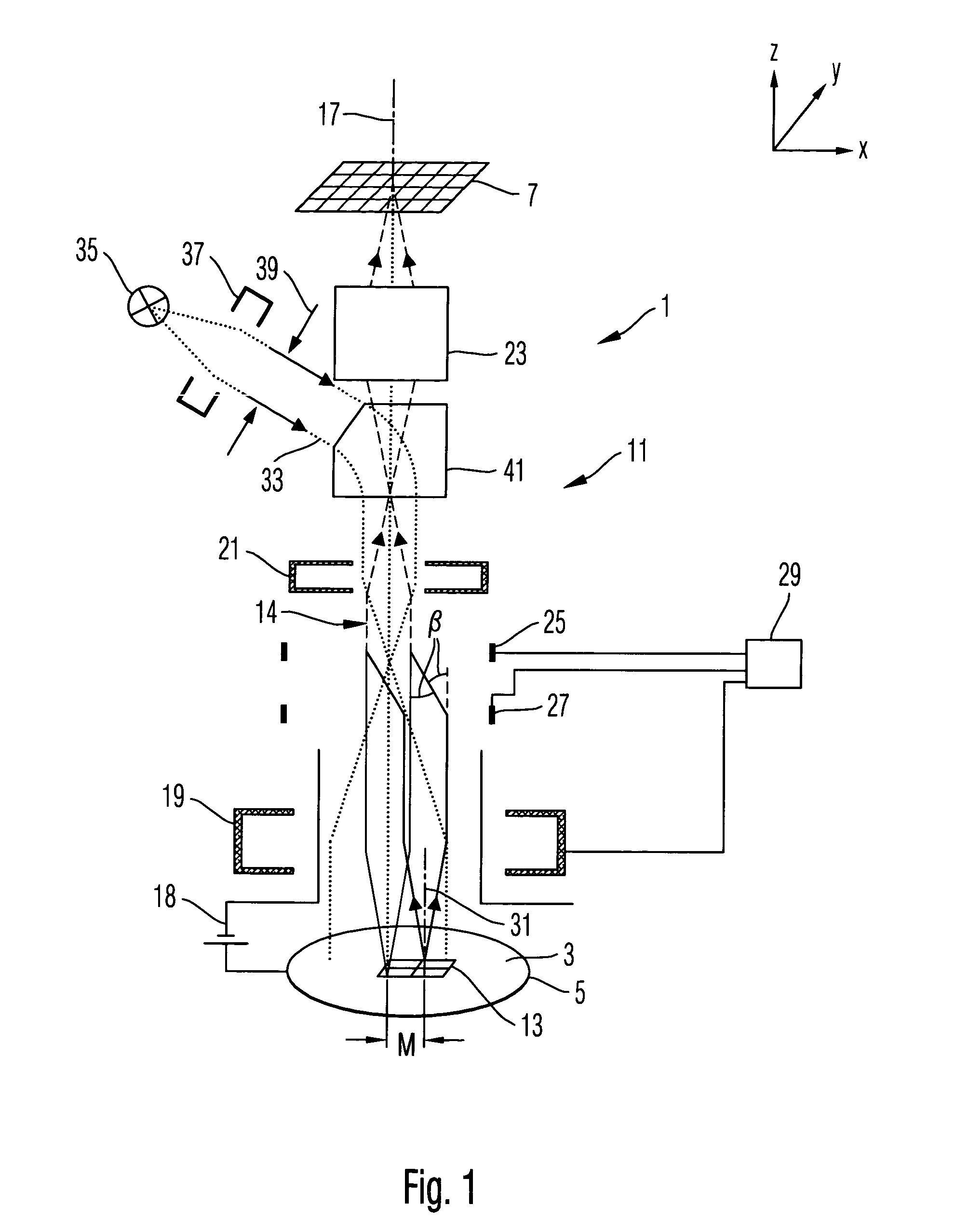
[0026] FIG. 1 schematically shows a microscopy system 1 for imaging a semiconductor wafer 5 positioned in an object plane 3 of the microscopy system 1 onto a position-sensitive detector 7. To this end, the microscopy system 1 comprises a microscopy optics 11 which provides a beam path for secondary electrons to electron-optically image a region 13 of the object plane 3 onto the detector 7. The beam path used for imaging the region 13 which is imaged onto the detector 7 is displaceable parallel to an optical axis 17 of the microscopy system 1 (in FIG. 1 a displacement is designated by M).

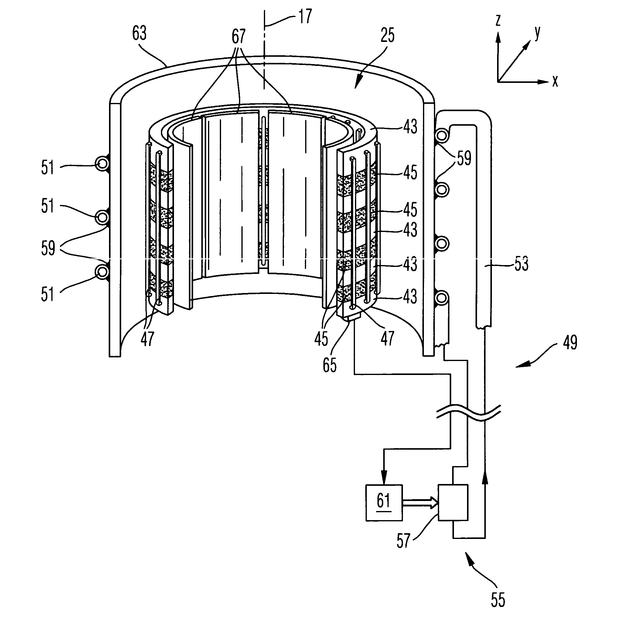
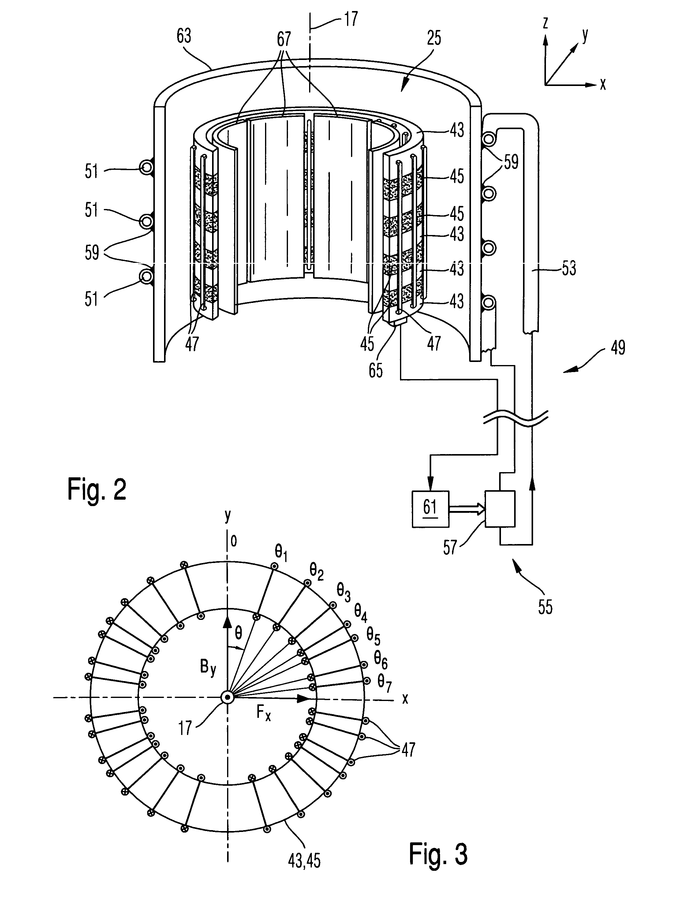
[0027] The microscopy optics 11 comprises a plurality of components which are symmetrically disposed centrally in respect of the optical axis 17, namely an objective lens 19, a field lens 21 and a further magnification optics 23. Between the objective lens 19 and the field lens 21, there are provided two beam deflectors 25 and 27 spaced apart from each other along the optical axis 17. The deflectors ...


PUM


Abstract

A particle-optical apparatus is proposed as well as a method for operating the same. The particle-optical apparatus provides a magnetic field for deflecting charged particles of a beam of charged particles and comprises a body of a material with a permeability number around which a current conductor at least partially engages and a temperature-adjusting unit -for adjusting a temperature of the magnetic-flux-carrying body substantially to a nominal temperature. A relative variation of the permeability number relative to a width of a temperature range is to be smaller than a limit value a, wherein a is preferably smaller than 3.10<-3>K<-1>. In particular, the nominal temperature is at an extremum of a temperature dependence of the permeability number. Preferably, such a particle-optical apparatus can be employed in a microscopy or a lithography apparatus.

Description

[0001] 1) Field of the Invention[0002] The present invention relates to a particle-optical apparatus for manipulating a beam of charged particles, a method for operating such a particle-optical apparatus, a microscopy system and a lithography system.[0003] 2) Brief Description of Related Art[0004] The particle-optical apparatus provides a magnetic field which the beam to be manipulated traverses. This manipulation may include a focusing, a deflection, a conversion of the beam or the like.[0005] Magnetic field configurations are known from the prior art which have a focusing, deflecting or converting effect on a beam of charged particles.[0006] For example, a beam deflector is known from U.S. Pat. No. 6,188,071 B1 for use in a lithography system. Here, a beam traversing the apparatus is an electron beam which is used as writing beam of the lithography system. A resolution of the lithography method performed therewith is thus determined also by the accuracy with which the deflection o...

Claims


Application Information

Patent Timeline
IPC IPC(8): H01J37/147H01L21/027
CPCH01J37/1475
Inventor CLAUSS, WILFRIED
Owner CARL ZEISS SMT GMBH
Why Eureka
Try Eureka