Cellular shade material for coverings for architectural openings

a technology of architectural openings and cellular shades, which is applied in the direction of shutters/movable grilles, door/window protective devices, transportation and packaging, etc., can solve the problems of cellular shades being typically expensive to manufacture, obstructive head rails, and not aesthetically pleasing

Inactive Publication Date: 2004-04-08
HUNTER DOUGLAS INC
View PDF7 Cites 34 Cited by
  • Summary
  • Abstract
  • Description
  • Claims
  • Application Information

AI Technical Summary

Problems solved by technology

It is possible that larger head rails could be utilized with a roller shade utilizing thick shade material, however, the head rail would likely be obtrusive and not aesthetically pleasing.
Cellular shades are typically expensive to ma...

Method used


Image

  • Cellular shade material for coverings for architectural openings
  • Cellular shade material for coverings for architectural openings
  • Cellular shade material for coverings for architectural openings

Examples


first embodiment

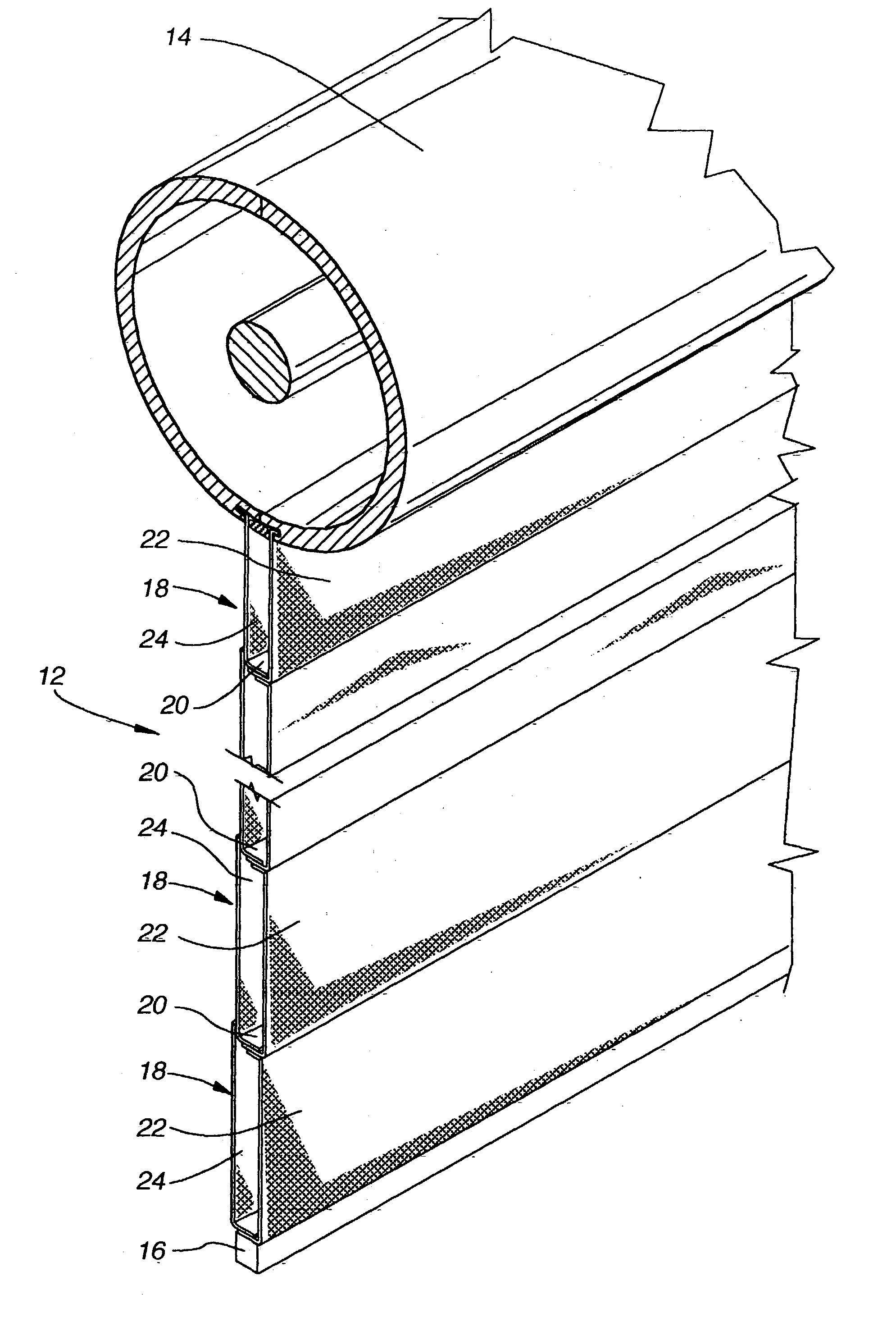
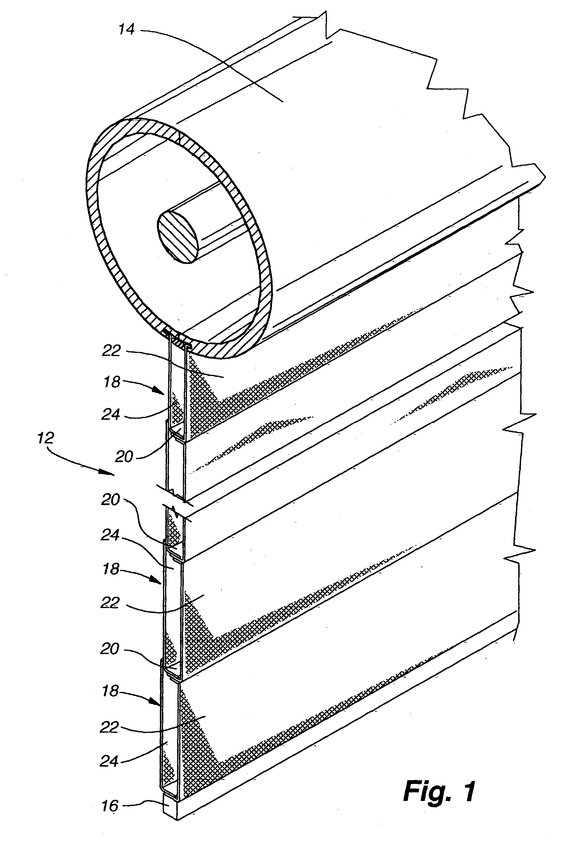
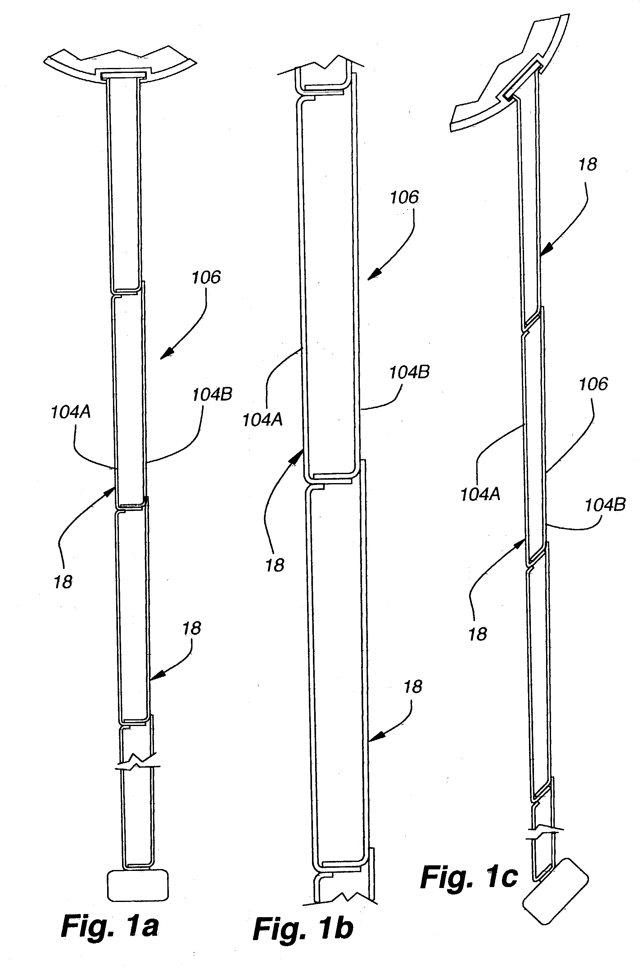
[0074] a fabrication apparatus for producing roller shade material 12 is illustrated in FIGS. 4-12 and 14-16. The fabrication apparatus includes a fabric tape supply section (supply section) 100, wherein fabric tapes 104 are unwound from rolls 102 and the tape is orientated for a subsequent folding operation. One or two rolls 102 of tape can be utilized. As shown in FIGS. 4 and 5, two fabric tapes 104 are unwound from separate rolls 102 and adhesively joined together for subsequent operations. One tape 104A forms primarily the front side 22 of the cells 18 of the resulting cellular shade material 12 and the other tape 104B forms primarily the back side 24 of the cells. The supply section 100 can also be configured with a single tape 104, wherein the tape forms both the front and back sides of the cells. The configuration and operation of the supply section is discussed in detail below.

[0075] After exiting the supply section, the joined tape 106 is passed into the folding and adhesiv...

second embodiment

[0140] The elongated drum 504 is best shown in FIGS. 38 and 39. The drum includes a central portion 532 with a surface onto which the folded tape 530 is laid to form the cellular shade material 12, and two end caps 534 that have a greater diameter than the central portion. The circumferential edges of the end caps support the drum against two elongated rollers 536 of the base 506 as the drum is rotated. In one variation of the second embodiment, the drum includes a center axle through which the drum is supported in bearing assemblies above the bottom surface of the base.

[0141] The base 506 is best shown in FIGS. 38, 39 and 40. The base has a pair of parallel recessed tracks 510 that extend substantially the entire length of the base in a direction parallel to the drum 504. The wheels 538 of the wheeled base 514 of the cart 502 are received in the tracks 510, which guide the cart as it moves along them. In-between the tracks, the rack 512 is secured to the base. The rack 512 interfac...


PUM


Abstract

An apparatus and method for fabricating a cellular roller shade material for use in roller shade coverings for architectural openings is described. In a preferred embodiment, two fabric tapes are joined proximate an edge of each to form a wide fabric tape. The wide fabric tape is then pulled through a folding horn to fold the tape along a longitudinal axis that is laterally offset from the tape's longitudinal axis. Two longitudinal adhesive beads are applied to the folded tape by an adhesive applicator. The folded tape is then continuously wound onto tubular surface with the surfaces of the folded tape containing the adhesive beads being placed in an overlapping relationship with a portion of a previously wrapped section of the folded tape. The wrapped and joined tubular tape is cut to form a sheet of shade material that comprises plurality of horizontally-extending cells when utilized in a roller shade.

Description

[0001] This application is a non-provisional application which claims the benefit of U.S. provisional application Serial No. 60 / 383,346, filed May 24, 2002, which application is incorporated by reference herewith in its entirety.[0002] 1. Field of the Invention[0003] This invention relates generally to a fabrication apparatus and method for fabricating coverings for architectural openings. More specifically, the invention relates to a fabrication apparatus and method for fabricating cellular material from fabric tape for use in roller shade coverings.[0004] 2. Background Description[0005] Roller shades are well known in the art and typically comprise a fabric shade material that hangs down from a roller and has a foot rail attached to its bottom edge. The roller is typically contained in a head rail that is attached to a vertical surface. As desired the shade material can be rolled up onto the roller to expose the architectural opening (typically, a window) beneath it.[0006] In gene...

Claims


Application Information

Patent Timeline
IPC IPC(8): E06B9/26E06B9/34E06B9/40
CPCE06B9/26E06B9/34Y10T428/24149E06B2009/2627E06B9/40
Inventor AUGER, RAYMONDASHURST, GARYBIRCH, CLIFF
Owner HUNTER DOUGLAS INC
Why Eureka
Try Eureka