Method of baking ceramic honeycomb structure

a technology of ceramic honeycomb and honeycomb, which is applied in the direction of silencing apparatus, machines/engines, domestic applications, etc., can solve the problems of large temperature difference, thermal stress inside the formed material, and defects such as cracks, and achieve the effect of strikingly shortening the conventional firing time and preventing firing defects

Inactive Publication Date: 2005-11-17
NGK INSULATORS LTD
View PDF11 Cites 20 Cited by
  • Summary
  • Abstract
  • Description
  • Claims
  • Application Information

AI Technical Summary

Benefits of technology

[0006] The present invention has been made in view of the above problems and aims at providing a method for firing of ceramic honeycomb structure, which ha

Problems solved by technology

In such a process for producing a honeycomb structure using a binder, however, there has been a problem that, during the firing of the formed material, there appear firing defects such as crack and the like.
The reason for the problem is considered to be that, during the firing of the formed material, a large temperature difference arises between the central portion of the formed material where

Method used


Image

  • Method of baking ceramic honeycomb structure
  • Method of baking ceramic honeycomb structure
  • Method of baking ceramic honeycomb structure

Examples


examples

[0058] The present invention is described more specifically below by way of Examples. However, the present invention is in no way restricted by these Examples. Incidentally, in the following Examples and Comparative Examples, there was used, as the average particle diameter of the used raw material for aggregate particles, a 50% particle diameter obtained by a measurement using a particle size distribution tester of X-ray transmission type (for example, Sedigraph 5000-02 produced by Shimadzu Corporation) which conducts detection by the X-ray transmission method based on the Stokes' liquid phase sedimentation method.

[Production of Formed Honeycomb Materials]

(Formed Material A)

[0059] As a raw material for aggregate particles, there was prepared a raw material to become cordierite, by mixing 40% by mass of talc (average particle diameter: 10 μm), 35% by mass of kaolin (average particle diameter: 10 μm), 10% by mass of alumina (average particle diameter: 6 μm), 10% by mass of alumin...

examples 1-1 to 1-4

and Comparative Examples 1-1 to 1-14

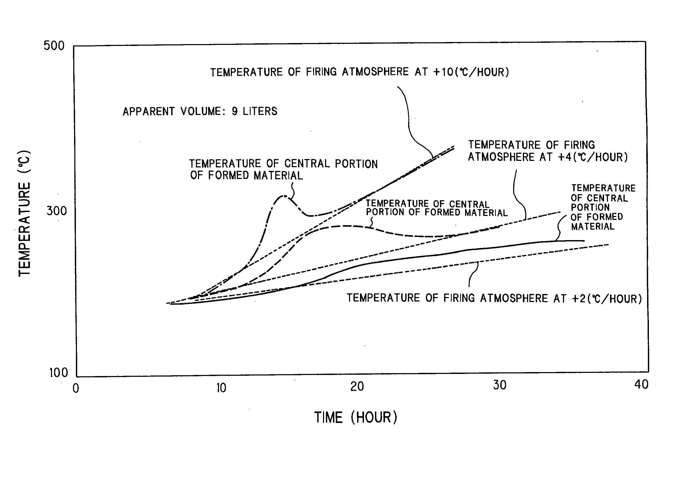
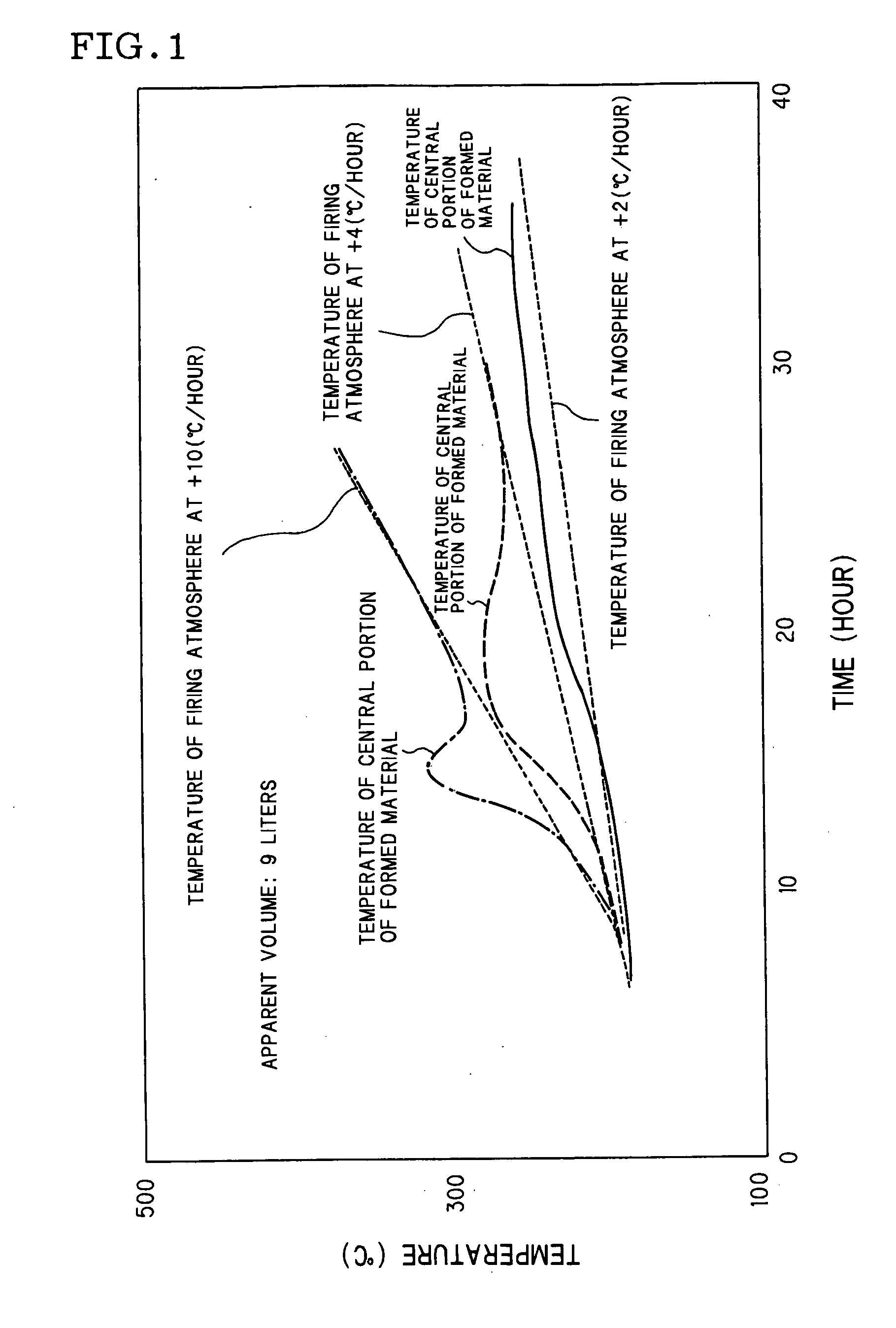
[0068] The formed honeycomb materials (formed materials A to C) were fired each under the conditions shown in Table 1 to investigate the influence of the temperature elevation rate of firing atmosphere in the temperature range (180 to 300° C.) of binder burning, on the defects of firing such as crack and the like and the time of firing. Incidentally, the firing was conducted using a batch type oven.

[0069] In Table 1, the temperature elevation rate of firing atmosphere in the temperature range of binder burning was expressed as “180 to 300° C. temperature elevation rate”; the maximum temperature difference in the temperature range of binder burning, of the temperature of central portion of formed material from the temperature of firing atmosphere was expressed as “180 to 300° C. maximum temperature difference”; the temperature elevation rate of firing atmosphere in the temperature range of talc dehydration was expressed as “800 to 1,000 temperatur...

examples 2-1 to 2-9

and Comparative Examples 2-1 to 2-6

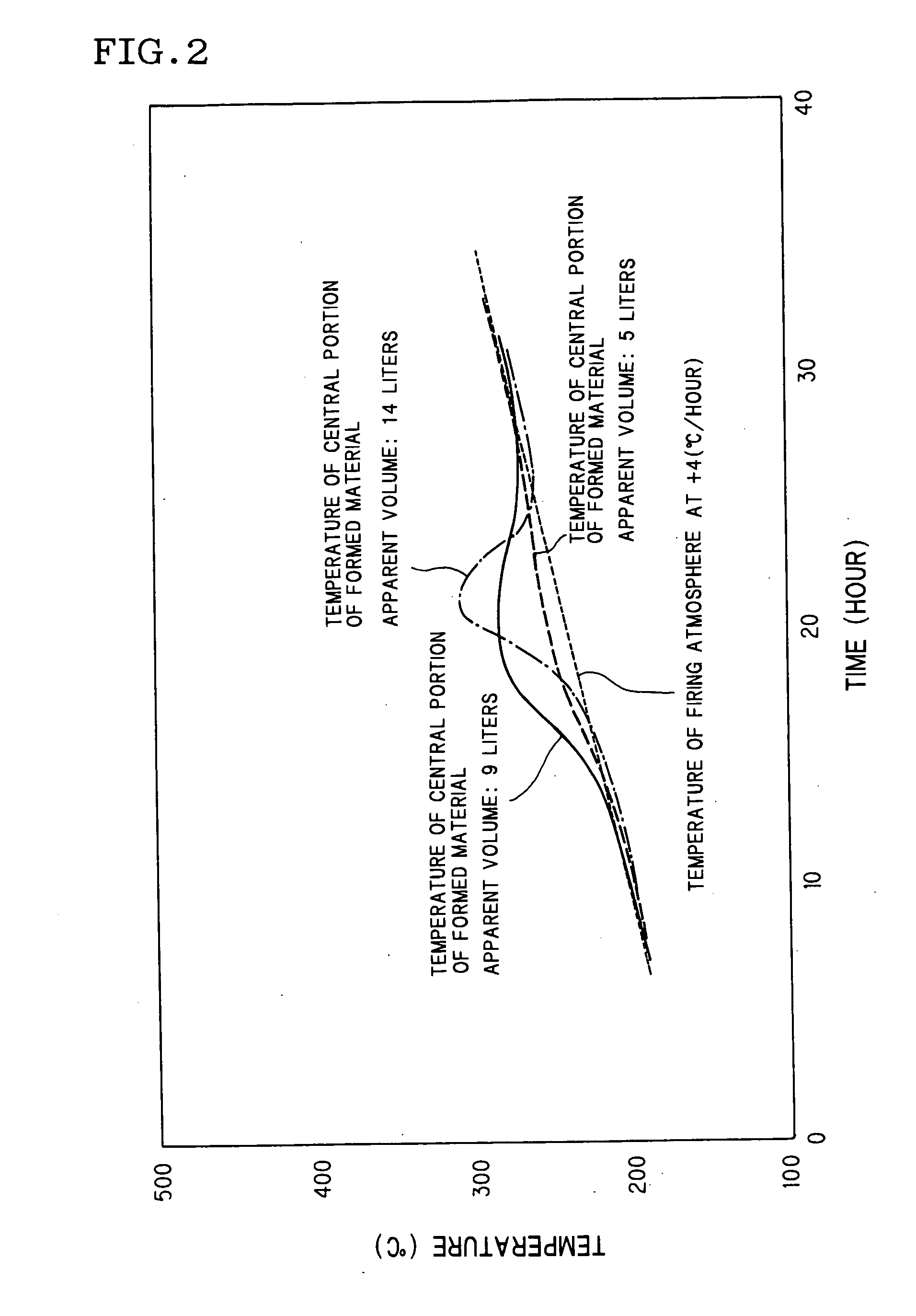
[0078] The formed honeycomb materials (formed materials A to C) were fired each under the conditions shown in Table 2 to investigate the influence of the temperature elevation rate of firing atmosphere in the temperature range (800 to 1,000° C.) of talc dehydration, on the defects of firing such as crack and the like and the time of firing. Incidentally, the firing was conducted using a batch type oven.

[0079] In Table 2, the temperature elevation rate of firing atmosphere in the temperature range of binder burning was expressed as “180 to 300° C. temperature elevation rate”; the maximum temperature difference in the temperature range of binder burning, of the temperature of central portion of formed material from the temperature of firing atmosphere was expressed as “180 to 300° C. maximum temperature difference”; the temperature elevation rate of firing atmosphere in the temperature range of talc dehydration was expressed as “800 to 1,000° C. tem...


PUM

PropertyMeasurementUnit
Temperatureaaaaaaaaaa

Abstract

In the method for firing of ceramic honeycomb structure according to the present invention, when a formed honeycomb material having an apparent volume of 5 liters or more is fired in a firing atmosphere, the heating of the firing atmosphere from a temperature (180 to 300° C.) at which the organic binder contained in the formed honeycomb material begins to burn, to 300° C. is conducted at a temperature elevation rate of +25 (° C./hr) or more and also at such a temperature elevation rate that the difference of the temperature of the central portion of the formed honeycomb material from the temperature of the firing atmosphere is kept in a given temperature range.

Description

TECHNICAL FIELD [0001] The present invention relates to a method for firing of ceramic honeycomb structure, which comprises firing a formed honeycomb material to obtain a ceramic honeycomb structure, particularly to a method for firing of ceramic honeycomb structure, which, when a large-sized formed honeycomb material having an apparent volume of 5 liters or more is fired, can effectively prevent firing defects such as cracks and the like and further can shorten the conventional firing time strikingly. BACKGROUND ART [0002] In various fields of chemistry, electric power, steel, industrial waste disposal, etc., ceramic honeycomb structures superior in heat resistance and corrosion resistance are in use as a dust-collecting filter for purposes such as environmental protection (e.g. pollution control), product recovery from high-temperature gas, and the like. For example, a diesel particulate filter (DPF) for capture of particulates emitted from a diesel engine is used under severe con...

Claims


Application Information

Patent Timeline
IPC IPC(8): B01D39/00F01N3/02B01D39/20B28B1/00C04B35/195C04B35/638C04B35/64C04B38/00
CPCC04B35/195C04B38/0009C04B2235/3217C04B2235/3218C04B2235/3418C04B2235/3445C04B2235/6567C04B2235/349C04B2235/5436C04B2235/6562
Inventor NAKAMURA, TOMOONOGUCHI, YASUSHI
Owner NGK INSULATORS LTD
Why Eureka
Try Eureka