
Process for producing ceo2 fine particles and polishing slurry containing such fine particles

Inactive Publication Date: 2007-09-06
ASAHI GLASS CO LTD
View PDF7 Cites 11 Cited by
  • Summary
  • Abstract
  • Description
  • Claims
  • Application Information

AI Technical Summary

Benefits of technology

[0024] According to the present invention, CeO2 fine particles having high crystallinity, excellent in uniformity of composition and particle size, and having a small particle size, can easily be obtained. Thus, using such fine particles, a polishing slurry suitable for precision polishing in a process for producing a semiconductor device can be provided. Further, as the fine particles have a small particle size, there are such advantages that the firing temperature can be lowered and the firing time can be shortened in the production process. Further, the fine particles are effective also as a polishing material for glass such as an optical disk, a substrate for a magnetic disk, a substrate for display or an optical lens.
[0025] Further, the fine particles are suitably used also as an ultraviolet absorber for an ultraviolet-absorbing glass or an ultraviolet-absorbing film, a gas sensor or an electrode material for a solid oxide fuel cell.

Problems solved by technology

That is, as the multilayered wirings are increasingly formed due to the miniaturization and densification in the semiconductor production processes, the degree of irregularities tends to increase in the surfaces of the individual layers, resulting in a situation where the step height exceeds the depth of focus in lithography.
Since the vapor pressure of copper chloride gas is low, it is difficult to form Cu into the shape of wirings by Reactive Ion Etching (RIE) which has been conventionally used.
For example, an attempt has been made to use a polishing compound in the form of a slurry containing ultrafine particles of high purity CeO2 for the above process for producing a semiconductor device (e.g. Patent Document 2) However, since CeO2 in a low crystalline state is chemically highly reactive, when a polishing compound slurry containing such CeO2 ultrafine particles is used, problems such as a burned spot, orange peel and deposition on the polished surface tend to arise, and thus they cannot be used for precision polishing.
However, in this method, it is not easy to set the reaction conditions, and it is hard to control the end point of the reaction, and accordingly, it is difficult to control the particle size of the fine particles and the particle size distribution, and no sufficient properties were achieved for use as a precision polishing slurry in the process for producing a semiconductor device.

Method used


Image

  • Process for producing ceo2 fine particles and polishing slurry containing such fine particles
  • Process for producing ceo2 fine particles and polishing slurry containing such fine particles

Examples


examples

[0049] Now, the present invention will be described in detail with reference to Examples. However, it should be understood that the present invention is by no means restricted to such specific Examples.

(1) Preparation of CeO2 Fine Particles

examples 1 to 17

[0050] Cerium oxide (CeO2), RCO3 (R=Ba and / or Sr) and boron oxide (B2O3) were weighed in the proportion shown in Table 1 as represented by mol % based on CeO2, RO and B2O3, respectively, a small amount of ethanol was added, and they were mixed and pulverized in an automatic mortar. Then, the mixture was dried to obtain a material powder.

[0051] The obtained material powder was put in a crucible with a nozzle, made of platinum containing 10 mass % of rhodium, and heated in an electric furnace employing molybdenum silicide as a heating element at 1,500° C. for one hour so that the material powder was completely melted.

[0052] Then, the melt was cast while the bottom of the is nozzle was heated in the electric furnace, and made to pass through twin rollers having a diameter of about 15 cm, rotating at 300 rpm to quench the droplets at a level of 1×10⁵° C. / sec to obtain a flaky solid. The obtained flakes were a brownish-red transparent amorphous material. The thickness of the flakes was...

examples 18 to 24

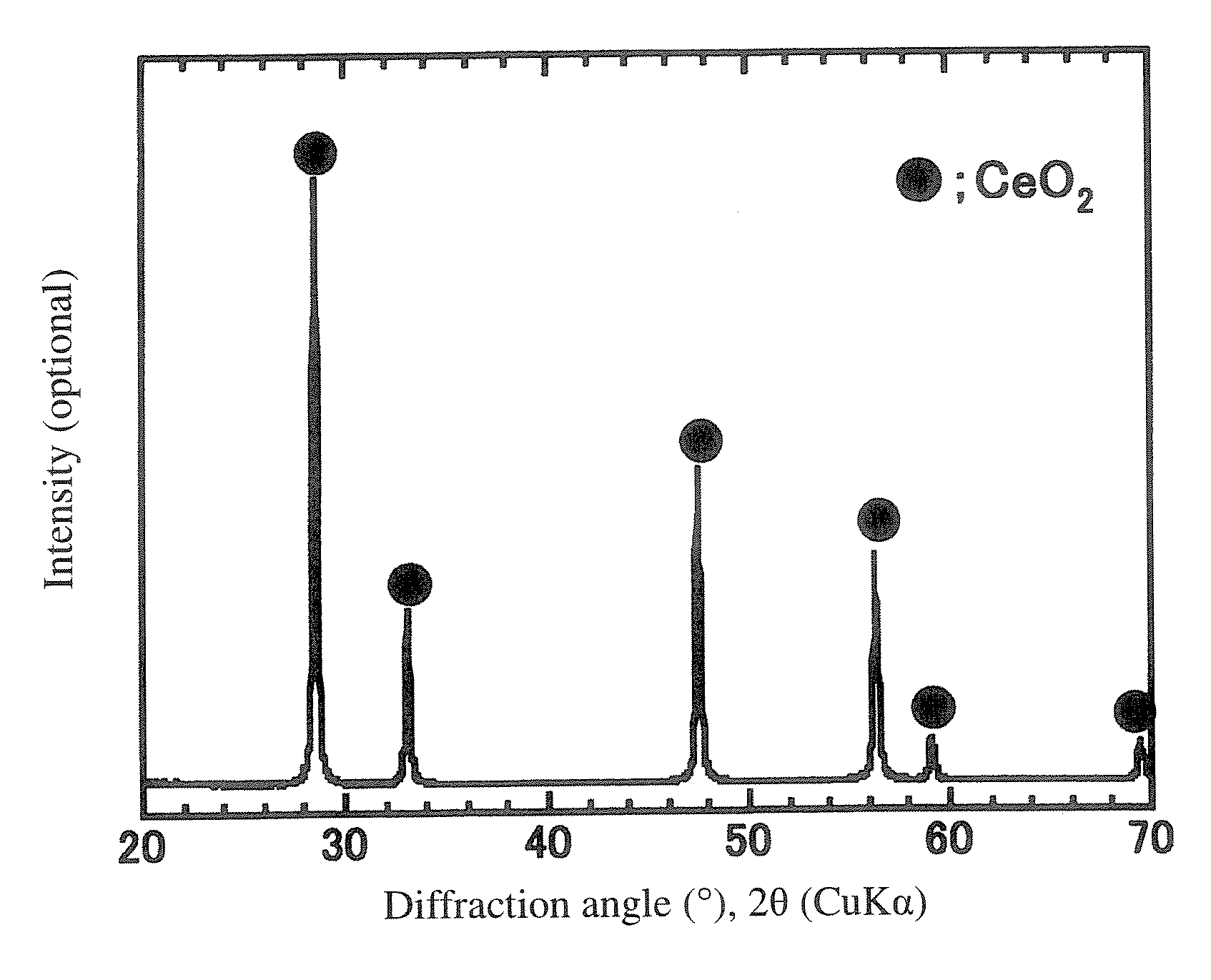
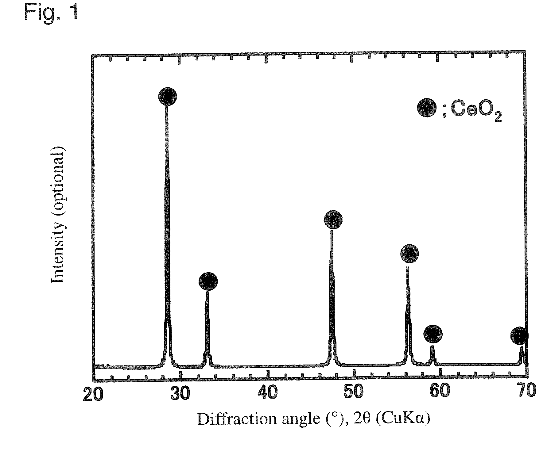
[0057] CeO2 fine particles were obtained in the same manner as in Example 1 except that the chemical composition of the material mixture was changed to the proportion shown in Table 2 and that the flakes were heated at the crystallization temperature shown in Table 2 for 8 hours. The mineral phase of the obtained CeO2 fine particles was identified in the same manner as in Example 1 and as a result, the fine particles were particles with high crystallinity consisting of a CeO2 single phase. Further, the crystallite diameter of the obtained fine particles was measured in the same manner as in Example 1 and as a result, the obtained fine particles had a very small particle size in each Example as is evident from Table 2. Further, an increase of the crystallite diameter along with the increase of the crystallization temperature was confirmed.

TABLE 2ChemicalCrystallizationCrystallitecompositiontemperature (° C.)diameter (nm)Ex.18Same as Ex.567015Ex.19Same as Ex.570024Ex.20Same as Ex.57...


PUM

PropertyMeasurementUnit
Temperatureaaaaaaaaaa
Fractionaaaaaaaaaa
Fractionaaaaaaaaaa

Abstract

To provide a process for producing CeO2 fine particles having high crystallinity, being excellent in uniformity of composition and particle size and having a small particle size, and a polishing slurry containing such fine particles. A process for producing CeO2 fine particles, which comprises a step of obtaining a melt containing, as represented by mol % based on oxides, from 5 to 50% of CeO2, from 10 to 50% of RO (wherein R is at least one member selected from the group consisting of Mg, Ca, Sr and Ba) and from 30 to 75% of B2O3, a step of quenching the melt to obtain an amorphous material, a step of precipitating CeO2 crystals from the amorphous material, and a step of separating the CeO2 crystals from the obtained crystallized product, in this order. A polishing slurry containing from 0.1 to 20 mass % of such fine particles.

Description

TECHNICAL FIELD [0001] The present invention relates to a process for producing CeO2 fine particles and a polishing slurry containing such fine particles. Particularly, it relates to a process for easily obtaining CeO2 fine particles having high crystallinity, being excellent in uniformity of composition and particle size, and having a small particle size, and a polishing slurry containing such fine particles. BACKGROUND ART [0002] Recently, particularly along with the increase in the integration and functionality of semiconductor integrated circuits, there has been a demand for development of micro-fabrication techniques for miniaturization and densification. Planarization techniques for interlayer insulating films and embedded wirings are important in semiconductor device production processes, in particular, in the process of forming multilayered wirings. That is, as the multilayered wirings are increasingly formed due to the miniaturization and densification in the semiconductor ...

Claims


Application Information

Patent Timeline
IPC IPC(8): B24D3/02C01F17/00C01F17/235
CPCB82Y30/00C01F17/0043C01P2002/60C01P2002/72H01L21/31053C01P2004/64C09G1/02C09K3/1427C09K3/1463C01P2004/62C01F17/235
Inventor BEPPU, YOSHIHISASAKAI, TOMOHIROKASHIWABARA, SATOSHISUNAHARA, KAZUO
Owner ASAHI GLASS CO LTD
Learn More