Electron diffraction system for use in production environment and for high pressure deposition techniques

a technology of diffraction system and production environment, applied in the field of improved electron source, can solve the problems of affecting the design, affecting the operation, and affecting the operation of the electron source, so as to improve the beam adjustment capability, avoid the disadvantages of the conventional system, and improve the beam adjustment stability

Active Publication Date: 2004-04-08
STAIB INSTR
View PDF13 Cites 5 Cited by
  • Summary
  • Abstract
  • Description
  • Claims
  • Application Information

AI Technical Summary

Benefits of technology

0013] An object of the invention is to provide an improved electron source avoiding disadvantages of the conventional systems. In particular, a system is to be provided offering improved beam adjustment capabilit...

Problems solved by technology

It is however strongly limited for the following new applications in particular in wafer production devices and in high pressure environment:
Many growth equipments work at higher gas pressure in the chamber, and often use reactive and/or toxic substances.
The filament will be also damaged from ions produced in the gas inside the source.
Accordingly, the main problems of the conventional systems result from: 1--a la...

Method used


Image

  • Electron diffraction system for use in production environment and for high pressure deposition techniques
  • Electron diffraction system for use in production environment and for high pressure deposition techniques
  • Electron diffraction system for use in production environment and for high pressure deposition techniques

Examples


Embodiment Construction

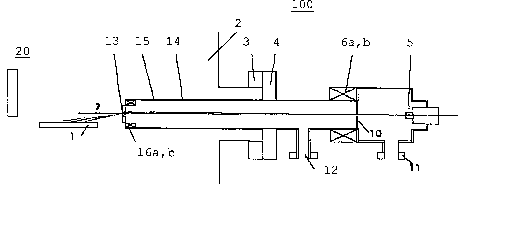
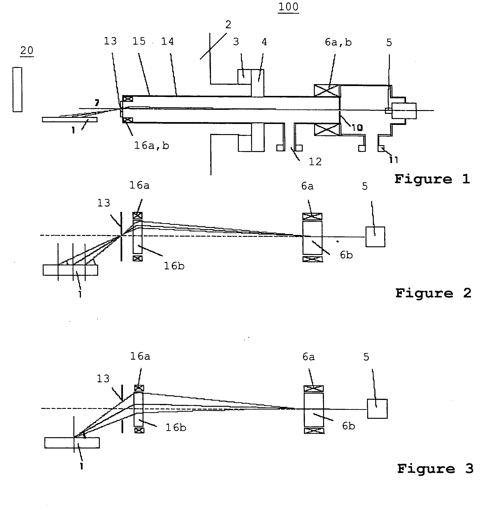
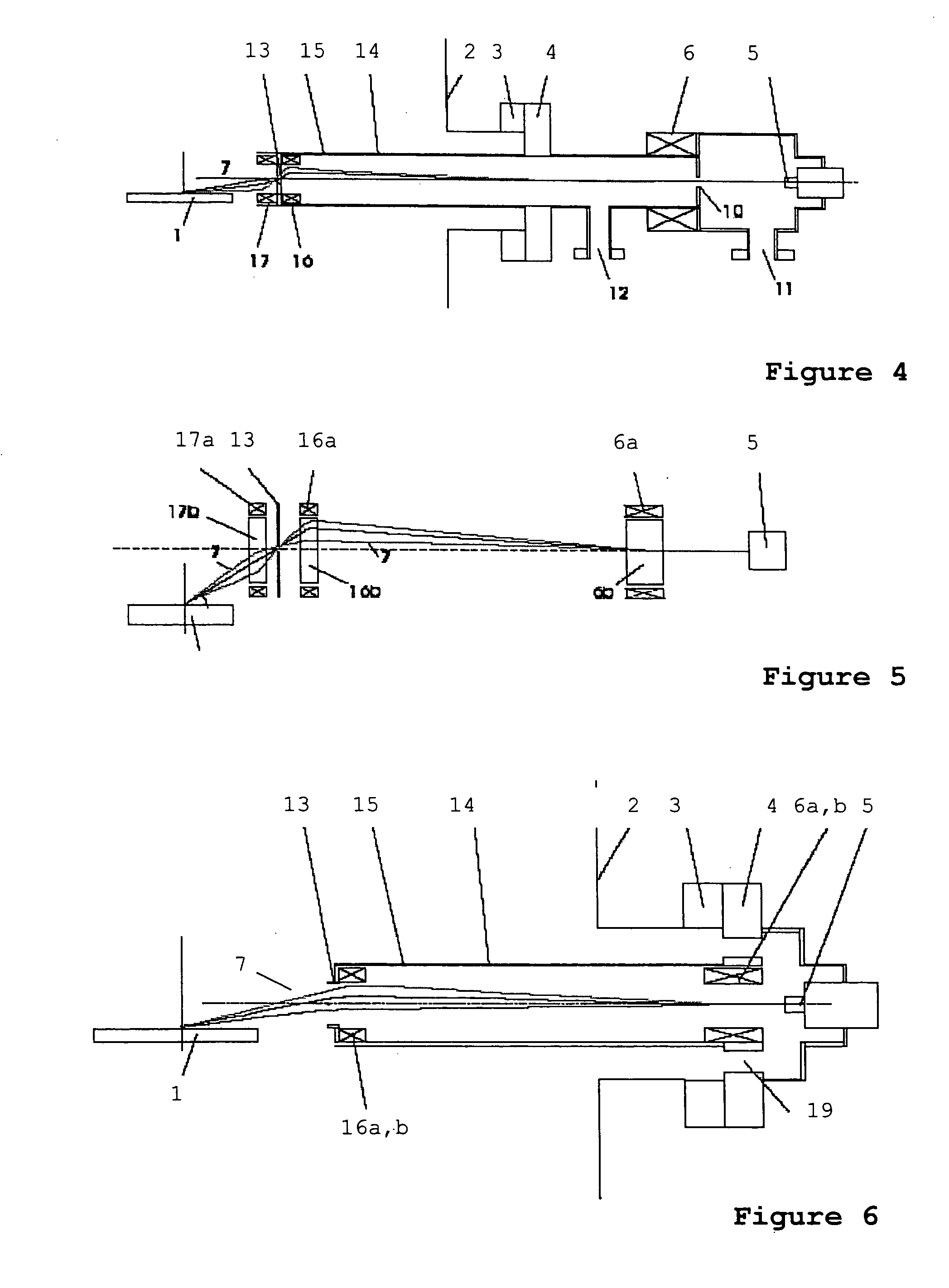
[0027] A first embodiment of an electron source 100 is shown in FIG. 1. The electron source 100 has a basic structure like a conventional system as shown in FIG. 8. Corresponding parts are indicated with corresponding reference numerals. The electron emitter 5 (electron gun) with a first deflection stage 6a,b is mounted via flanges 3, 4 to a vacuum chamber 2 (shown in part). The line from the electron emitter 5 to the first deflection stage 6a,b defines an axis of the electron source. The vacuum chamber 2 is a recipient of a deposition apparatus or a measuring device, for example. The electron source 5 is adapted for irradiating a sample 1 (e.g. a wafer) within the vacuum chamber e.g. for a RHEED measurement. A pumping port 11 is provided for differentially pumping the emitter volume.

[0028] According to the invention, a second deflection stage 16a,b is added to the system. The second deflection stage 16a,b is arranged between the first deflection stage 6a,b and the sample 1, i.e. on...


PUM


Abstract

An electron source particularly for a RHEED measurement system or a RHEED measurement system as such includes an electron emitter (5), a first deflection stage (6a, b) for radiating an electron beam onto a sample (1), and a second deflection stage between the first stage (6a, b) and the sample 1, preferably near the sample.

Description

[0001] The present invention relates to an electron source, in particular for a RHEED measurement system, as well as a RHEED measurement system as such, and a method of radiating an electron beam with an electron source onto a sample.[0002] The diffraction of electrons on a crystal surface is in many aspects similar to the optical diffraction of light or X-rays. The Bragg's diffraction law applies for both and governs the appearance and size of the diffraction diagram. The two essentials parameters of the incident beam are found in Bragg's diffraction law, i.e. its wavelength and the incidence angle. As the wavelength associated to electrons is small and comparable or smaller to the lattice spacing of atoms in crystals, electron diffraction, as X-ray diffraction, is used to analyze the atomic structure of materials. Because electrons are strongly absorbed, they cannot penetrate or be transmitted through the sample. Unlike for X-ray diffraction, the electron beam diffraction is perfo...

Claims


Application Information

Patent Timeline
IPC IPC(8): G01Q30/12G01Q30/20H01J37/295
CPCH01J37/295
Inventor STAIB, PHILIPPE
Owner STAIB INSTR
Why Eureka
Try Eureka