Method and device for the representing an object by means of an irradiation and for reconstructing said object

a technology of object representation and object reconstruction, applied in the field of objects representation, can solve the problems of unmeasurably low intensities, erroneous and incomplete projection data, and the subsequent automatic image evaluation of image data 908 with the aim of error recognition seriously impeded

Inactive Publication Date: 2004-04-08
FRAUNHOFER GESELLSCHAFT ZUR FOERDERUNG DER ANGEWANDTEN FORSCHUNG EV
View PDF8 Cites 27 Cited by
  • Summary
  • Abstract
  • Description
  • Claims
  • Application Information

AI Technical Summary

Problems solved by technology

It is one problem of computer tomography that, when the object 903, such as an industrial device under test has a combination of a high absorption density on the one hand and a large radiation path on the other hand, such as when strongly absorbing material lands are present in the device under test, even in a small part of the radiation directions necessary for the reconstruction means 906 for computer tomographical reconstruction, this high absorption often leads to unmeasurably low intensities and consequently to erroneous and incomplete projection data, respectively, in the reconstruction data 904 due to the limited usable detector dynamic of the computer tomograph 900.
Generally, due to these artifacts, any subsequent automatic image evaluation of the image data 908 with the aim of error recognition is seriously impeded.
Additionally, the missing areas in the reconstructed image increase the effort for the following error recognition based on the reconstructed image.
In transmission directions, for example, which generate areas of very high absorption and thus faulty areas in the measured data, despite optimum setting of the measuring parameters and optimum planning of the measuring geometry, the areas in the projection data, which are highly noisy and inaccurate due to the high absorption, are replaced by simulated data, which are, for example, captured from a CAD model of the device under test.

Method used


Image

  • Method and device for the representing an object by means of an irradiation and for reconstructing said object
  • Method and device for the representing an object by means of an irradiation and for reconstructing said object
  • Method and device for the representing an object by means of an irradiation and for reconstructing said object

Examples


Embodiment Construction

[0021] It should be noted that the following description of the present invention refers merely exemplarily to an embodiment, wherein the transmissions of the object are performed via an X-ray computer tomograph, and wherein the object to be tested is a device under test, such as an artificial limb to be tested. The invention can be applied, for example, to other computer tomography methods, such as positron emission tomography (PET) or to other transmission methods, wherein advance information and previous knowledge, respectively, can be used for the optimization of the setting of the adjustment of measuring parameters or for the subsequent supplementation and replacement of the measured data for an improvement of a subsequent reconstruction.

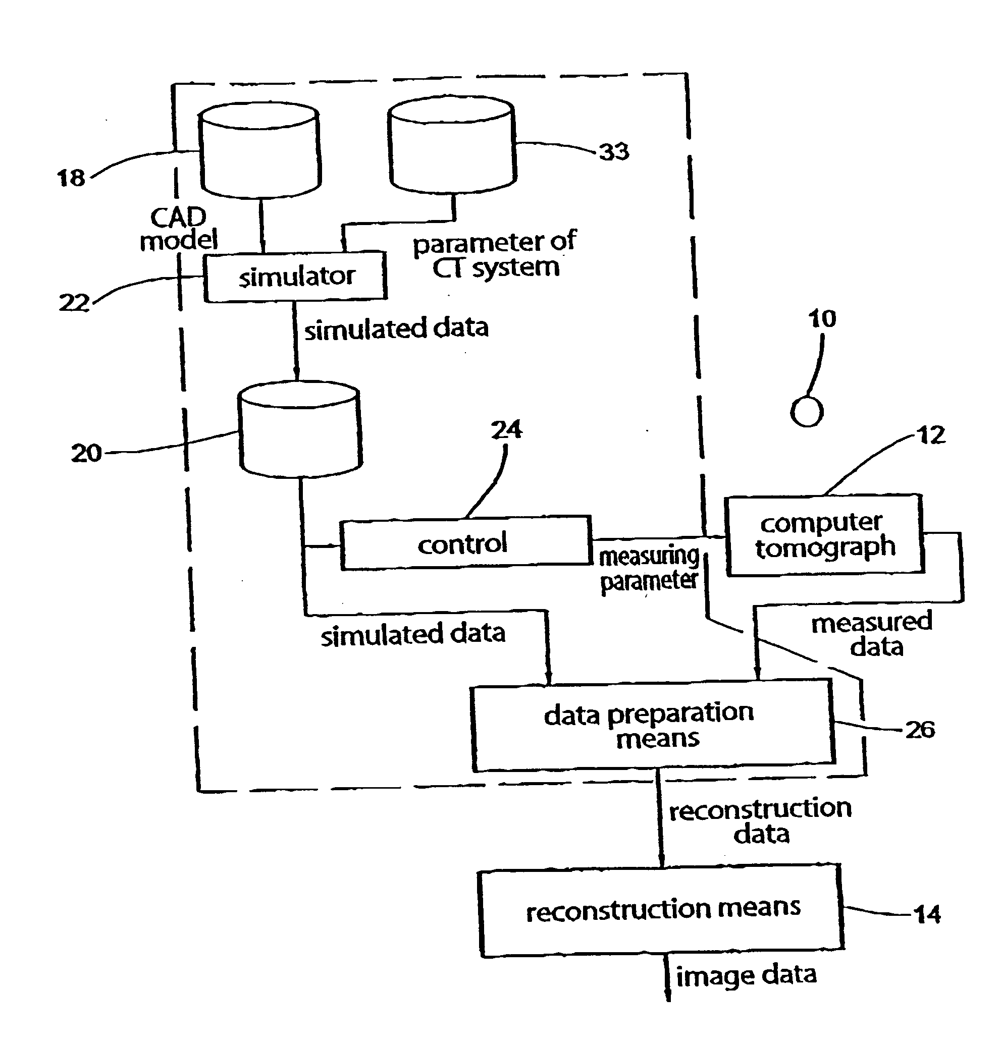
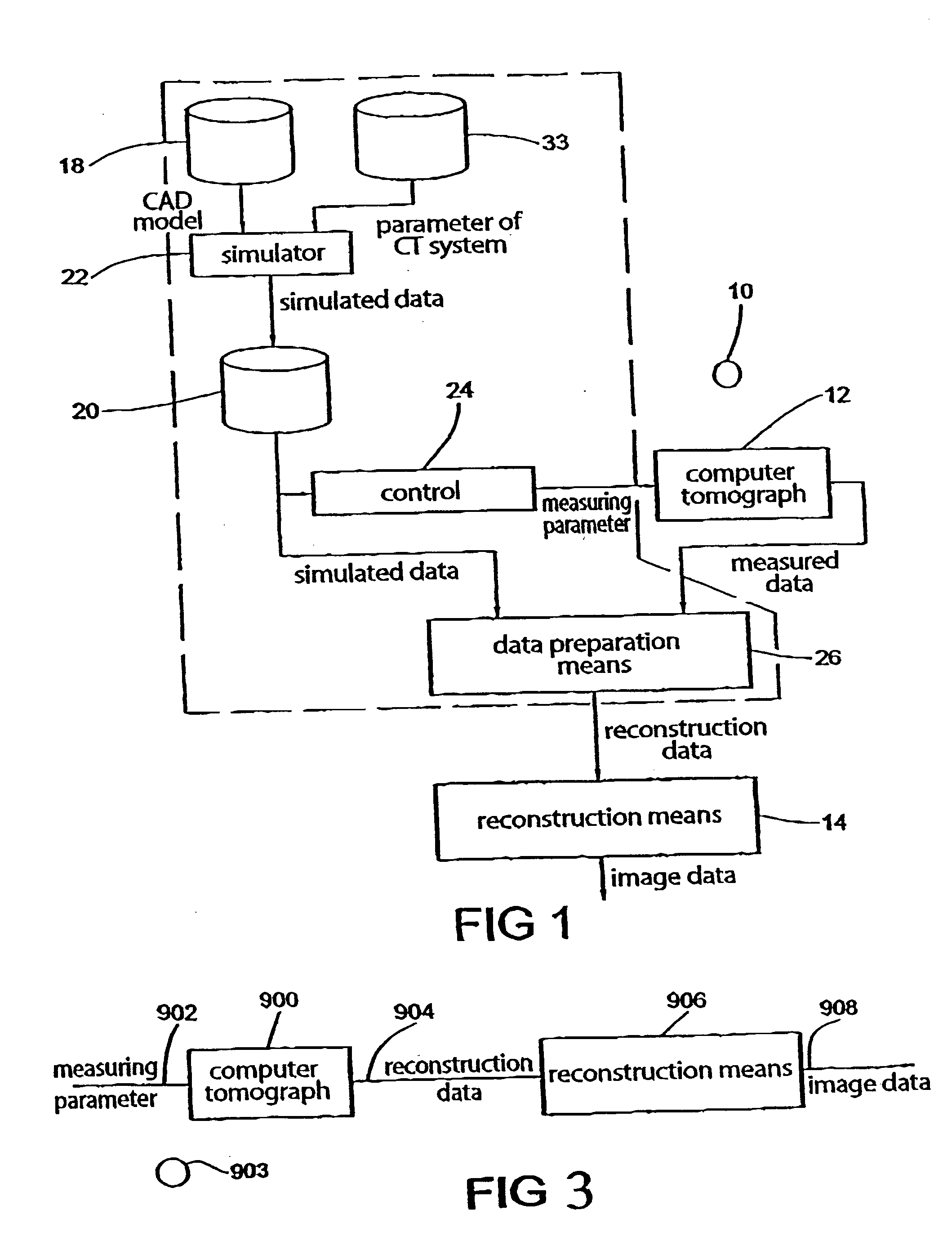
[0022] FIG. 1 shows the construction of an apparatus for a computer tomographical reconstruction of an object according to an embodiment of the present invention. According to the present embodiment, the apparatus is provided to test a device u...


PUM


Abstract

The invention is based on the knowledge that a representation of an object can be improved via a transmission with regard to a subsequent reconstruction of the object based on the representation, by using simulated data, which correspond to a simulated transmission of the object already prior to a reconstruction as advance information for measuring a transmission of the object and / or for generating the representation from a measured transmission. An inventive method for the representation of an object via a transmission comprises providing simulated data, which correspond to a simulated transmission of the object, for example in a memory, and using the simulated data for measuring a transmission of the object, for example in a computertomograph, to obtain the transmission of the object, by a control and / or using the simulated data for generating the representation from a measured transmission by a data preparation means.

Description

[0001] 1. Field of the Invention[0002] The present invention refers to the representation of objects via a transmission and to the reconstruction of an object based on such a representation of the object, such as it is the case in computer tomography.[0003] 2. Description of Prior Art[0004] Computer tomography has been developed in the 70 ties and is based on the reconstruction of an object based on projections of the object from different transmission directions. Every projection level gives information about an absorption and extinction distribution, respectively, of the object transversal to the transmission direction. The object can be determined with regard to its extinction properties and its density, respectively, from the projections of different transmission directions.[0005] In an X-ray computer tomograph, for example, an X-ray tube and an X-ray detector opposite to the X-ray tube across the object, which consists of a row and a circle segment of sensors, respectively, rot...

Claims


Application Information

Patent Timeline
Patent Type & Authority Applications(United States)
IPC IPC(8): G06T11/00
CPCG06T11/005A61B6/5258
Inventor HANKE, RANDOLFSCHROPFER, STEFANGERHAEUSER, HEINZPAULUS, DIETRICH
Owner FRAUNHOFER GESELLSCHAFT ZUR FOERDERUNG DER ANGEWANDTEN FORSCHUNG EV
Why Eureka
Try Eureka