Synchronization error detection circuit

a technology of synchronization error and detection circuit, which is applied in the direction of synchronization signal speed/phase control, recording signal processing, instruments, etc., can solve the problems of high accuracy, transmission channel errors, and errors

Inactive Publication Date: 2004-04-22
LAPIS SEMICON CO LTD
View PDF7 Cites 17 Cited by
  • Summary
  • Abstract
  • Description
  • Claims
  • Application Information

AI Technical Summary

Problems solved by technology

Due to the structure of the codes used, however, long burst errors present difficulties for FEC, while the CRC method can detect long burst errors with a fairly high degree of accuracy.
When the CRC method is used alone, or when the FEC method is used but an error that exceeds the FEC error-correcting capability is detected, a retransmission request is sent to the transmitting apparatus.
Errors may occur in the transmission channel for various reasons, including noise radiating from surrounding areas.
When the channel is a wireless channel, errors may also occur because the transmitting apparatus and receiving apparatus are too widely separated and the received radio signal is too weak.
Another possible cause is clock jitter in either the transmitting communication apparatus or the receiving communication apparatus.
If this assumption is not true, error control performance falls short of theoretical expectations.
In actual communication, this assumption is often false.
Imperfect synchronization can lead to errors kn...

Method used


Image

  • Synchronization error detection circuit
  • Synchronization error detection circuit
  • Synchronization error detection circuit

Examples


first embodiment

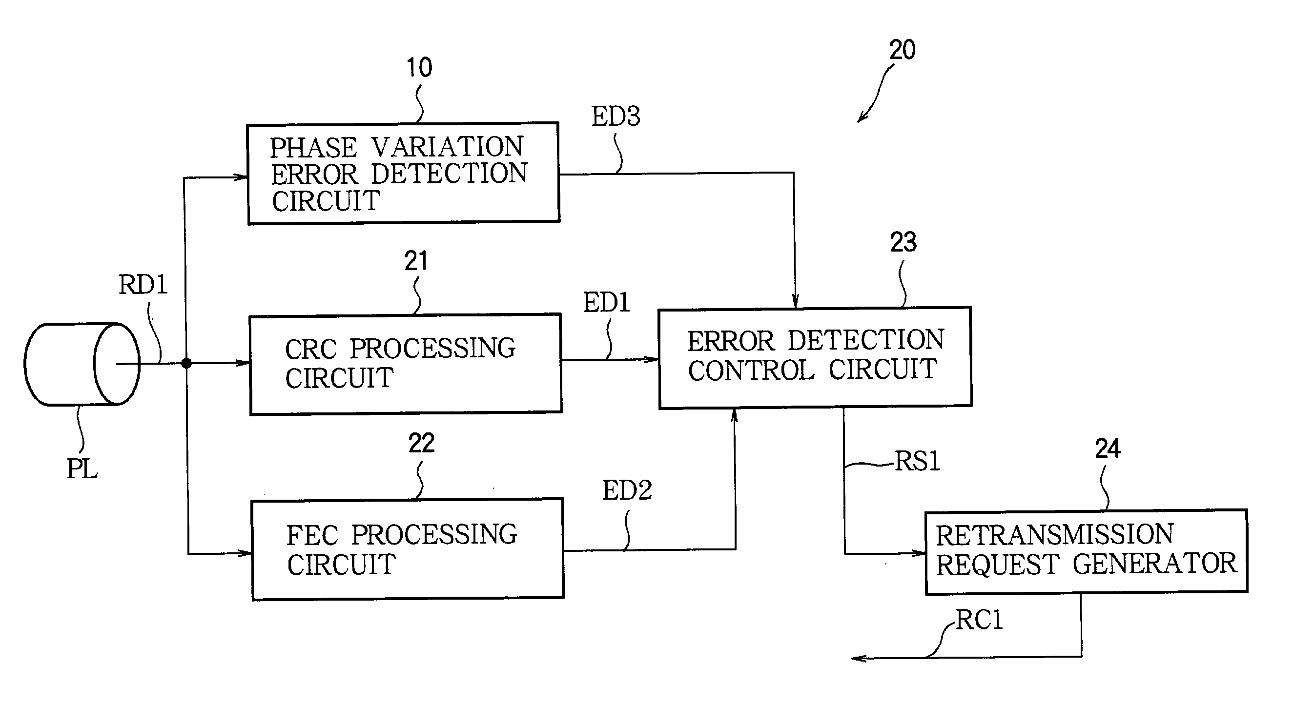
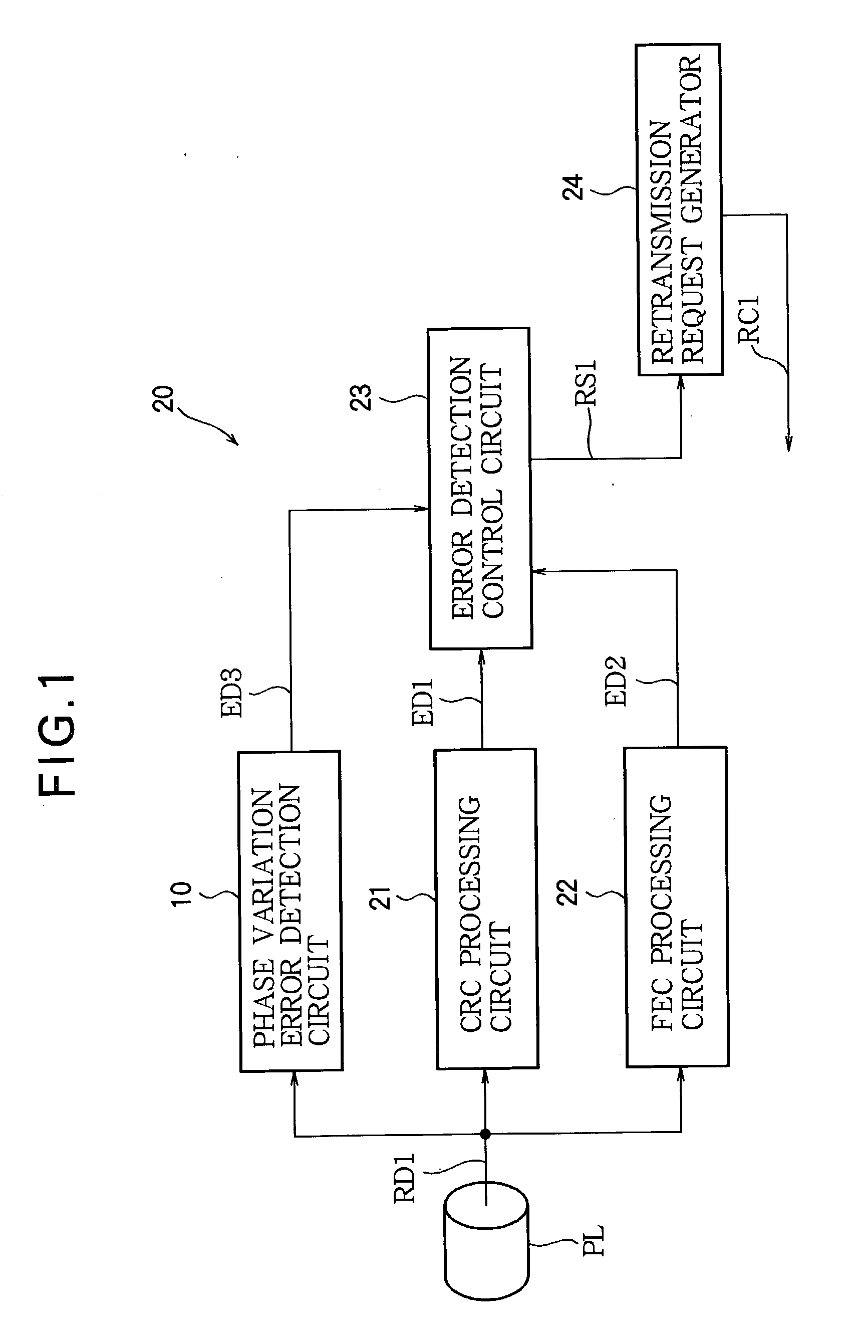
[0029] Referring to FIG. 1, the synchronization error detection circuit in the first embodiment is a phase variation error detection circuit 10 used in a communication apparatus 20 having a receiving function. The communication apparatus 20 also includes a CRC processing circuit 21, an FEC processing circuit 22, an error detection control circuit 23, a retransmission request generator 24, and other circuits, such as a clock recovery circuit (not shown), which are used in receiving data.

[0030] The communication apparatus 20 receives a data stream RD1 from a transmission channel such as a phone link PL. The received data stream RD1 is converted from analog to digital form and processed by various filters (not shown) and other necessary circuits, then supplied to the synchronization error detection circuit 10, CRC processing circuit 21, and FEC processing circuit 22. The transmission channel PL may be a wireless channel or a wireline channel, or a channel including both wireline and wi...

second embodiment

[0094] Referring to FIG. 6, the second embodiment replaces the phase variation error detection circuit of the first embodiment with a pulse width error detection circuit 50. The differences between the pulse width error detection circuit in the second embodiment and the phase variation error detection circuit in the first embodiment will be described below.

[0095] FIG. 7 shows an exemplary structure of the pulse width error detection circuit in the second embodiment, using the same reference characters as in FIG. 2 for similar elements. The pulse width error detection circuit 50 includes several of the same circuit elements as the phase variation error detection circuit 10 in the first embodiment, but differs from the phase variation error detection circuit by replacing the phase averaging circuit 15 with a pulse width measuring circuit 55, the phase variation error decision circuit 18 with a pulse width error decision circuit 58, and the phase variation threshold register 19 with a ...


PUM


Abstract

Synchronization errors in a received pulse train are detected by detecting rising or falling transitions in the pulse train, generating numbers in a repeating cycle having a length corresponding to the pulse rate, selecting the number generated when each transition is detected, and performing a predetermined operation on the selected numbers. The predetermined operation may include, for example, comparing the average values of the selected numbers in successive groups of transitions. Alternatively, the predetermined operation may include taking a difference between consecutively selected numbers to measure pulse widths in the pulse train. Synchronization error detection can be used to supplement data error detection and correction methods such as forward error correction and cyclic redundancy checks.

Description

[0001] 1. Field of the Invention[0002] The present invention relates to a circuit for detecting synchronization errors, and in particular to a circuit that can be usefully combined with a circuit that detects errors in data received in, for example, a digital wireless communication system.[0003] 2. Description of the Related Art[0004] The methods generally used for data error control in digital wireless communication systems include cyclic redundancy check (CRC) codes and forward error correction (FEC).[0005] CRC codes enable errors to be detected. Treating the individual bits of transmit data as the coefficients of a polynomial, the transmitting apparatus divides a block of transmit data by a predetermined generator polynomial, and redundantly appends the remainder to the block as a CRC code. The receiving apparatus divides the received block, including the appended CRC code, by the same generator polynomial, and checks that the result is zero. Output of a non-zero bit by the check...

Claims


Application Information

Patent Timeline
IPC IPC(8): H04L1/00H03M13/33H04L1/18H04L7/00H04L7/033H04L7/04
CPCH03M13/33H04L1/1812H04L7/043H04L7/033H04L7/0083
Inventor MIYAMOTO, HIROMITSU
Owner LAPIS SEMICON CO LTD
Why Eureka
Try Eureka