Energy absorber for interposing between a rigid beam and a bumper skin, and an energy-absorbing assembly

a technology of energy absorber and rigid beam, which is applied in the directions of bumpers, vehicle safety arrangments, transportation and packaging, etc., can solve the problems of high cost and achieve the effect of less expensive implementation

Inactive Publication Date: 2004-04-29
CO PLASTIC OMNIUM
View PDF9 Cites 11 Cited by
  • Summary
  • Abstract
  • Description
  • Claims
  • Application Information

AI Technical Summary

Benefits of technology

0012] The present invention seeks to propose a novel configuration for absorbers that comply with requirements concerning impacts in all of the above-mentioned categories of impact, but which is particularly simple and much less expensive to implement.

Problems solved by technology

One of the problems with such a stack is its cost, which is very high, particularly because of the cost of the foam and of the handling that is needed for putting it into place on the system.
Another problem results from the depth which is needed to make the layer of foam effective.

Method used


Image

  • Energy absorber for interposing between a rigid beam and a bumper skin, and an energy-absorbing assembly
  • Energy absorber for interposing between a rigid beam and a bumper skin, and an energy-absorbing assembly
  • Energy absorber for interposing between a rigid beam and a bumper skin, and an energy-absorbing assembly

Examples


Embodiment Construction

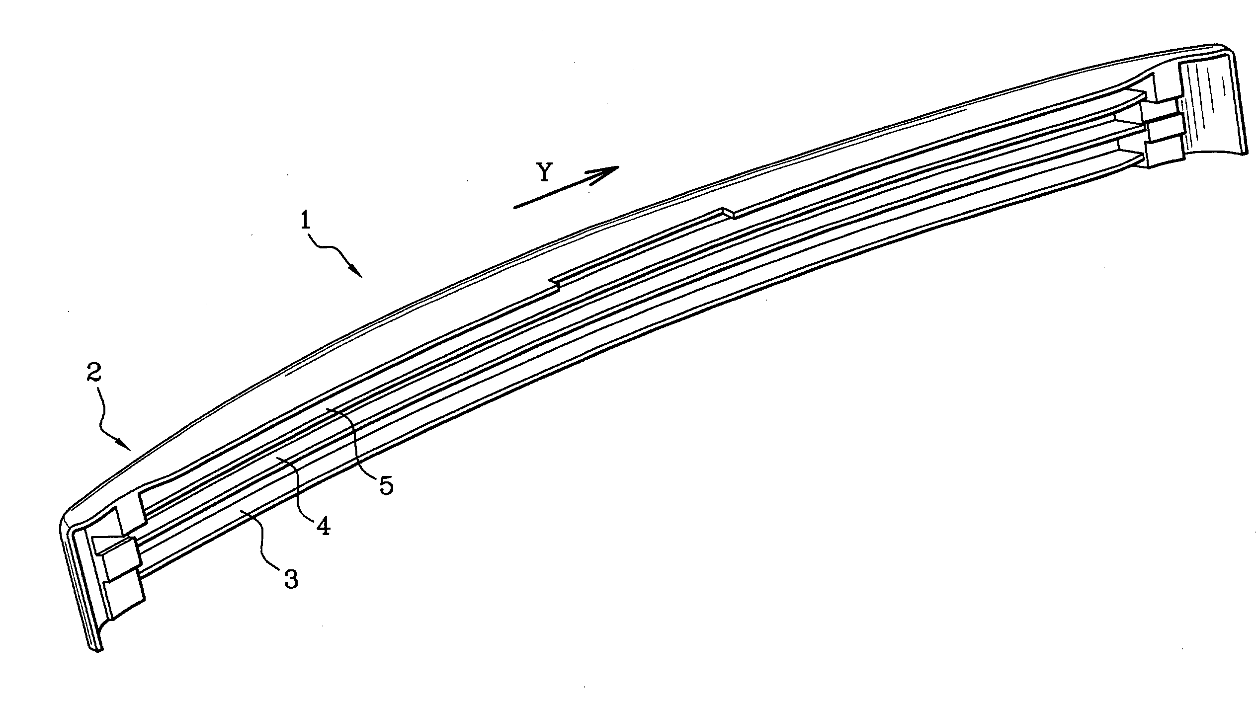
[0031] The energy absorber of FIG. 1 presents a longitudinal direction Y which corresponds to the transverse direction of the vehicle.

[0032] It is made by injecting polypropylene or polyethylene under conventional conditions for thermoplastic injection molding.

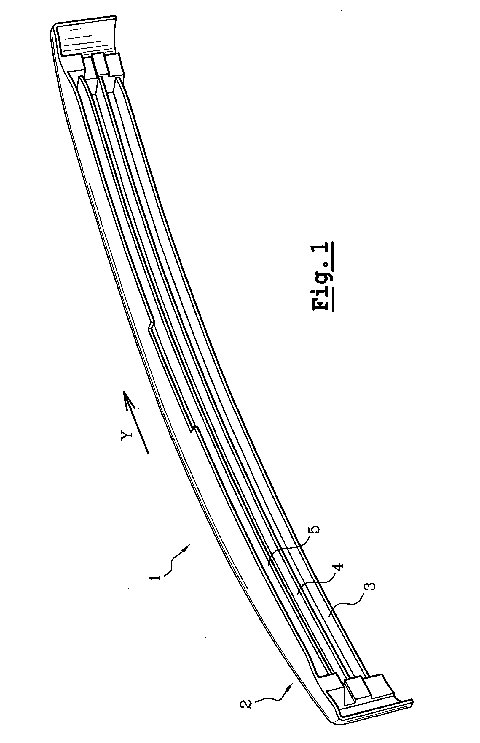
[0033] It has a front plate 2 and three longitudinal ribs or webs 3, 4, and 5 that are parallel to one another and horizontal when the energy absorber is mounted on a vehicle.

[0034] In the example shown, the top and bottom ribs 5 and 3 are themselves provided with vertical reinforcing ribs 6 occupying their base portions, and in this case extending over about half of each rib. The middle rib 4 does not have any vertical reinforcing rib.

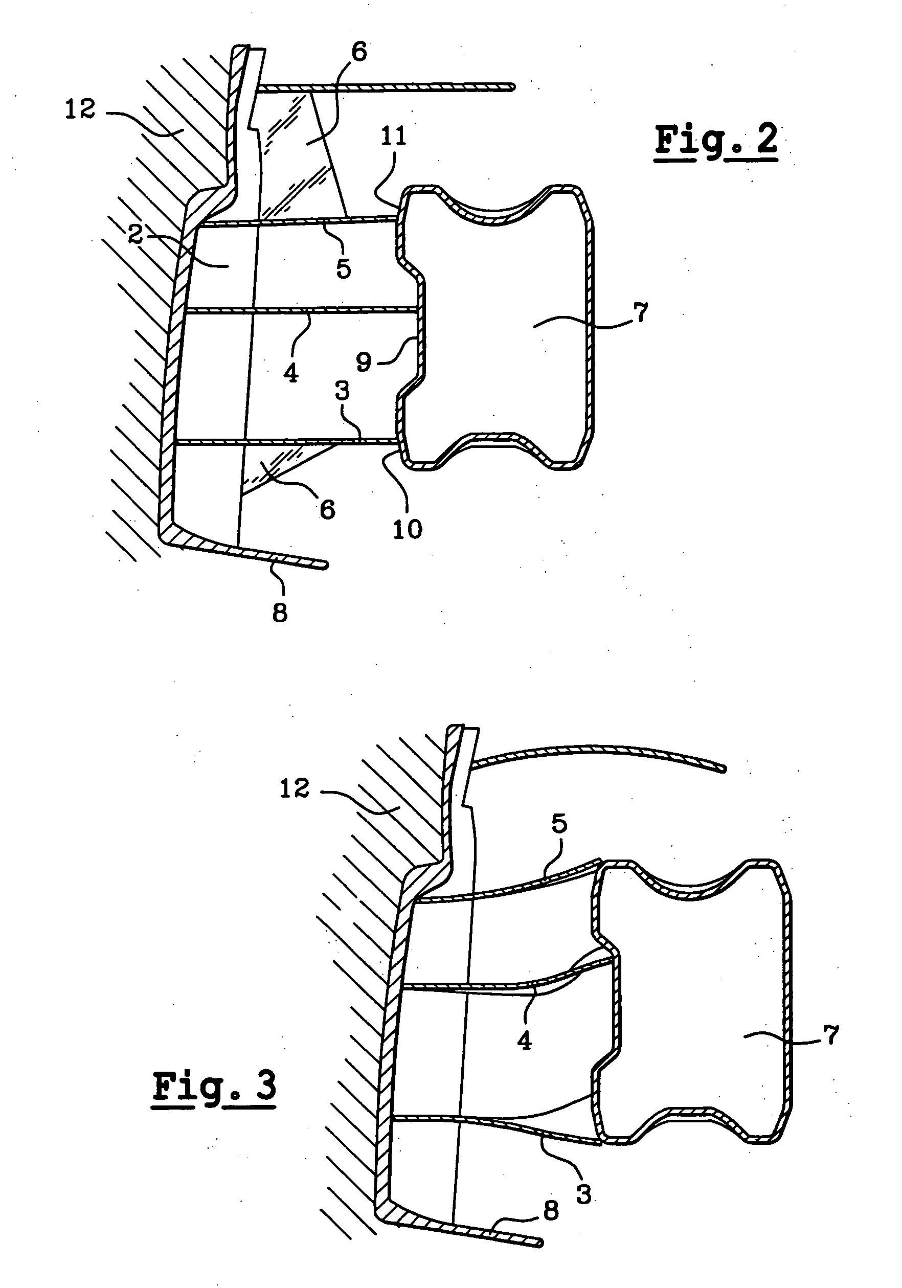
[0035] As can be seen more clearly in the section of FIG. 2, the middle rib 4 is slightly longer than the upper and lower ribs. This difference in length is justified by the shape of the impact beam 7 against which the energy absorber takes its position when mounted inside the skin of the bumper...


PUM


Abstract

The energy absorber is for interposing between a rigid beam and a bumper skin in order to absorb, by compression, the energy of impacts directed in a crumpling direction. The energy absorber comprises a set of ribs each of which extends parallel to the crumpling direction and each of which possesses a free edge for pressing against the beam. The set of ribs includes at least one rib arranged in the event of an impact so that its free edge remains pressed against the beam, while the rib itself buckles, and at least one other rib arranged in such a manner that in the event of an impact, its free end escapes from the beam, causing said rib to bend.

Description

[0001] The present invention relates to an energy absorber and to an assembly constituted by an energy absorber and a rigid beam.[0002] A bumper comprises an outer decorative covering, referred to as a "skin", and an inner system for absorbing energy which, by deforming, consumes as much as possible of the energy of an impact so as to transmit as little as possible thereof to the vehicle.[0003] In terms of impact, car manufacturers implement a set of specifications that envisage three categories of impact, namely: high speed impacts corresponding to a head-on impact of the vehicle against a rigid or deformable obstacle at a speed of 56 kilometers per hour (km / h) to 64 km / h, "insurance" impacts such as those known as "Danner" impacts, at 15 km / h against a fixed wall, and small impacts or "parking bumps" at a speed lying in the range 4 km / h to 8 km / h, such as defined in the standard ECE R42.[0004] High speed impacts are taken into consideration for the purpose of protecting the occupa...

Claims


Application Information

Patent Timeline
Patent Type & Authority Applications(United States)
IPC IPC(8): B60R19/18
CPCB60R19/18B60R2019/186B60R2019/1806
Inventor MALTESTE, STEPHANEROUSSEL, THIERRYROCHEBLAVE, LAURENTCAVILLON, THIERRY
Owner CO PLASTIC OMNIUM
Why Eureka
Try Eureka