Radar device and method for suppressing interference in a radar device

a radar device and interference suppression technology, applied in the direction of measurement devices, using reradiation, instruments, etc., can solve the problem of ambiguity in the determination of target distances outside the unambiguous range of pulsed radar devices

Inactive Publication Date: 2004-05-13
ROBERT BOSCH GMBH
View PDF8 Cites 17 Cited by
  • Summary
  • Abstract
  • Description
  • Claims
  • Application Information

AI Technical Summary

Problems solved by technology

However, ambiguities may occur in the determination of target distances outside of the unambiguous range of a pulsed radar device.
In addition, there is interference due to multiple puls

Method used


Image

  • Radar device and method for suppressing interference in a radar device
  • Radar device and method for suppressing interference in a radar device
  • Radar device and method for suppressing interference in a radar device

Examples


Embodiment Construction

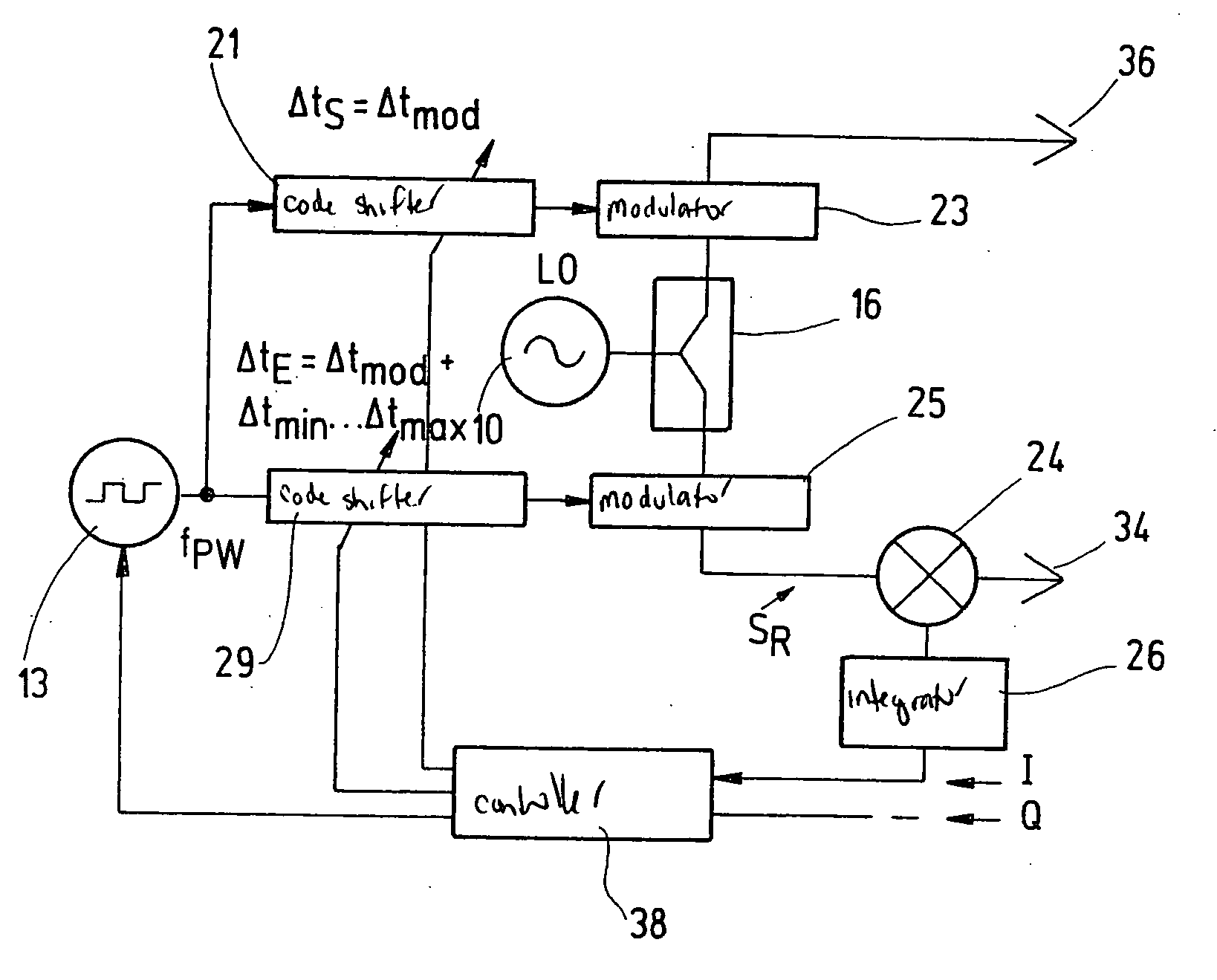
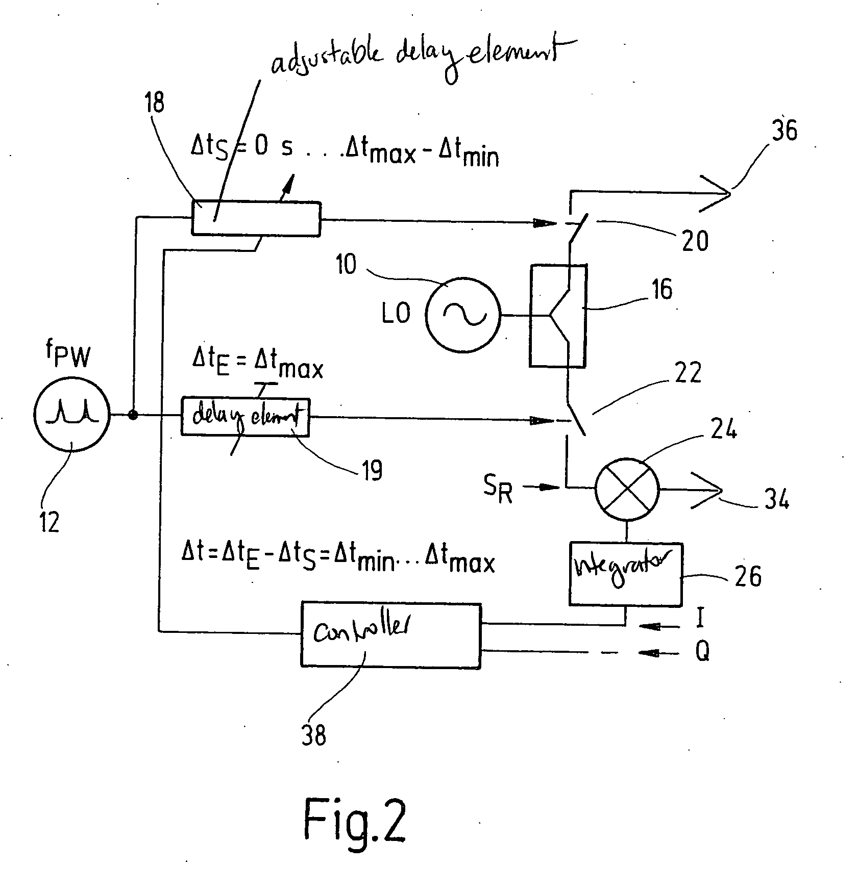
[0038] FIG. 2 shows a schematic diagram of a radar device according to the present invention. A local oscillator 10 is connected to a power divider 16. This power divider 16 is connected to a transmission branch. Part of the power of local oscillator 10 is output by power divider 16 into the reception branch. Furthermore, a pulse generator 12 is provided for generating pulse repetition rate f.sub.PW. The output of the pulse generator is connected to an adjustable delay element 18 and to an adjustable or non-adjustable delay element 19. The output of adjustable delay element 18 actuates a switch 20 in the transmission branch for modulating the carrier signal. The output signal of the adjustable or non-adjustable delay element 19 actuates a switch 22 in the reception branch for modulating the carrier signal in the reception branch and thus for providing a reference signal S.sub.R. The signal modulated by switch 20 in the transmission branch is sent by sending aerial 36 and reflected a...


PUM


Abstract

A radar device is described having means (10) for generating a carrier signal having a carrier frequency fT, means (12, 13, 15, 17) for generating pulses having a pulse repetition rate fPW, means (16) for splitting the carrier signal between a transmission branch and a reception branch, means (18, 19, 21, 27, 29) for delaying the pulses, means (24) for mixing the carrier signal in the reception branch with a reception signal and means (26) for integrating the mixed signal, whereby means (20, 23) for modulating the carrier signal in the transmission branch with the delayed pulses are provided and means for altering the delay in the pulses according to a predetermined code are provided. A method of suppressing interference with the functioning of a radar device is also described.

Description

[0001] The present invention relates to a radar device having means for generating a carrier signal having a carrier frequency f.sub.T, means for generating pulses having a pulse repetition rate f.sub.PW, means for splitting the carrier signal between a transmission branch and a reception branch, means for delaying the pulses, means for mixing the carrier signal in the reception branch with a reception signal and means for integrating the mixed signal. The present invention also relates to a method for suppressing interference with the functioning of a radar device, including the steps of generating a carrier signal having a carrier frequency f.sub.T, generating pulses having a pulse repetition rate f.sub.PW, splitting the carrier signal between a transmission branch and a reception branch, delaying the pulses, mixing the carrier signal in the reception branch with a reception signal and integrating the mixed signal.BACKGROUND INFORMATION[0002] Generic radar devices and methods are ...

Claims


Application Information

Patent Timeline
IPC IPC(8): G01S7/282G01S7/292G01S7/36G01S13/02G01S13/22
CPCG01S7/023G01S7/282G01S13/222G01S7/36G01S7/2921G01S7/0231G01S7/0234G01S7/0235
Inventor BROSCHE, THOMAS
Owner ROBERT BOSCH GMBH
Why Eureka
Try Eureka