Power-supply voltage frequency control circuit
a voltage frequency control and power supply technology, applied in the direction of generating/distributing signals, pulse technique, dynamo-electric converter control, etc., can solve the problems of interruption processing by timer, inability to ensure operation when operating system, and inability to complete tasks
- Summary
- Abstract
- Description
- Claims
- Application Information
AI Technical Summary
Problems solved by technology
Method used
Image

Examples
first embodiment
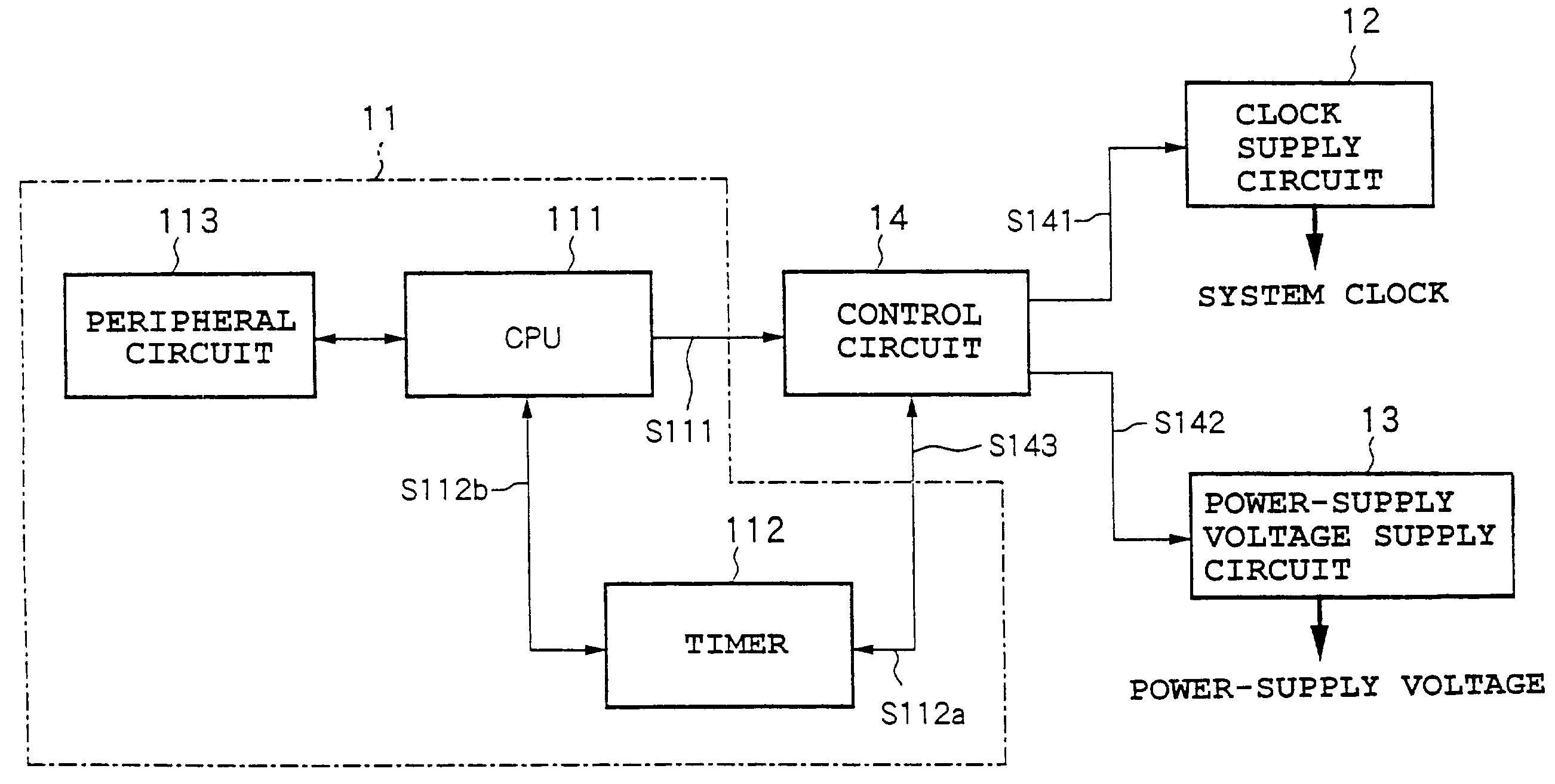
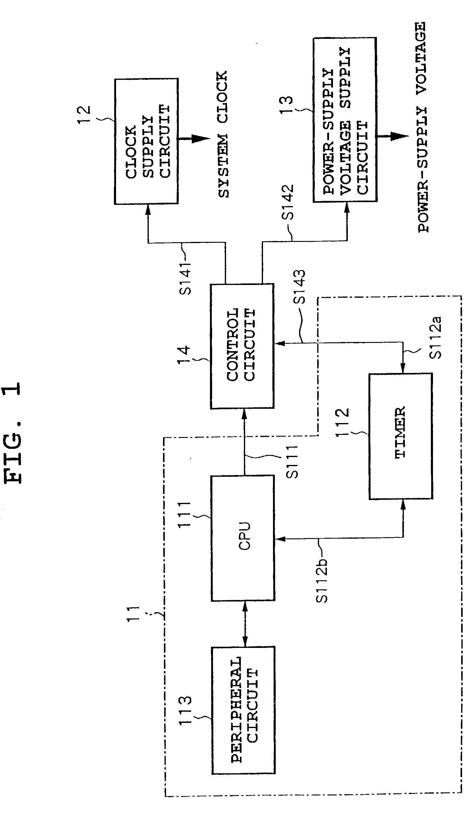
[0091] FIG. 1 is a block diagram of an electronic circuit system employing a power-supply voltage frequency control circuit according to the present invention.
[0092] The present circuit system 10 comprises, as shown in FIG. 1, a target circuit 11, a clock supply circuit 12, a power-supply voltage supply circuit 13, and a control circuit 14.
[0093] The target circuit 11 forms a system to be controlled by a clock frequency and a power-supply voltage V.sub.DD. As will be explained later on, it is supplied with a power-supply, voltage V.sub.DD from the power-supply voltage supply circuit 13 capable of supplying a minimum power-supply voltage for assuring operation of the system at the clock frequency, operates in synchronization with a system clock SYSCLK supplied from the clock supply circuit 12 capable of generating a multiple levels of clock frequency, and performs desired processing.
[0094] The target circuit 11 according to the first embodiment processes required tasks while working ...
second embodiment
[0147] FIG. 7 is a block diagram of a second embodiment of an electronic circuit system employing a power-supply frequency control circuit according to the present invention.
[0148] The present second embodiment is different from the first embodiment in the points that it is controlled by a control circuit 14 separate from a timer 112 communicating with a CPU 111 of the target circuit 11 and a timer 15 whose count the CPU 111 can read is independently arranged.
[0149] In the configuration of FIG. 1, modification is necessary to add to the timer 112 performing processing on a predetermined task related to the CPU 111 a comparator and a comparison register for the control circuit 14. However, if the circuit of the present invention is added to an existing system, modification of the timer is difficult in some cases. Also, depending on the task to be processed by the system, there are probably some cases where the timer has to be exclusively used.
[0150] In such a case, by separately arra...
third embodiment
[0151] FIG. 8 is a block diagram of a third embodiment of an electronic circuit system employing a power-supply voltage frequency control circuit according to the present invention.
[0152] The circuit system 20 comprises, as shown in FIG. 8, a target circuit 21, a clock pulse generation circuit 22, a frequency-voltage conversion circuit 23, a power-supply voltage generation circuit 24, a timer 25, and a frequency control circuit 26.
[0153] The target circuit 21 forms a system to be controlled by a clock frequency and a power-supply voltage V.sub.DD. As will be explained later on, it is supplied with a power-supply voltage V.sub.DD from the power-supply voltage generation circuit 24 capable of supplying the minimum power-supply voltage to assure the operation of the system at the clock frequency and operates in synchronization with a system clock SYSCLK supplied from the clock pulse generation circuit 22 capable of generating multiple levels of clock frequency to perform desired proces...
PUM
 Abstract
Description
Claims
Application Information
 - R&D
- Intellectual Property
- Life Sciences
- Materials
- Tech Scout
- Unparalleled Data Quality
- Higher Quality Content
- 60% Fewer Hallucinations
Browse by: Latest US Patents, China's latest patents, Technical Efficacy Thesaurus, Application Domain, Technology Topic, Popular Technical Reports.
© 2025 PatSnap. All rights reserved.Legal|Privacy policy|Modern Slavery Act Transparency Statement|Sitemap|About US| Contact US: help@patsnap.com