Filter, high-frequency module, communication device and filtering method

a technology of high-frequency modules and filters, applied in coupling devices, electrical devices, waveguides, etc., can solve the problems of limited miniaturization, large device size, and limit to miniaturization

Inactive Publication Date: 2004-05-20
PANASONIC CORP
View PDF8 Cites 24 Cited by
  • Summary
  • Abstract
  • Description
  • Claims
  • Application Information

AI Technical Summary

Problems solved by technology

As for this configuration, however, miniaturization of the device is limited because the length of the stripline resonators 181a and 181b is the 1 / 4-wavelength.
According to the above configuration, however, there is a limit to the miniaturization because, as it is constituted by using the two devices of the laminated filter and balun using the stripline resonators, the device size becomes large.
However, such a balun cannot have the attenuation band or attenuation pole provided in a desired frequency range.
In the case of connecting the balun and filter of the past technology, there is a problem that, as each of them includes a loss in the pass band, the loss is increased by combining them.

Method used


Image

  • Filter, high-frequency module, communication device and filtering method
  • Filter, high-frequency module, communication device and filtering method
  • Filter, high-frequency module, communication device and filtering method

Examples


first embodiment

[0222] (First Embodiment)

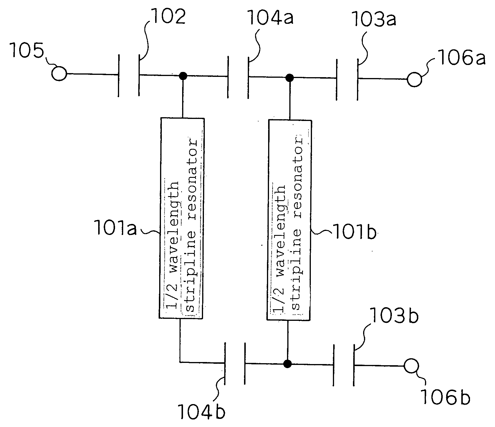
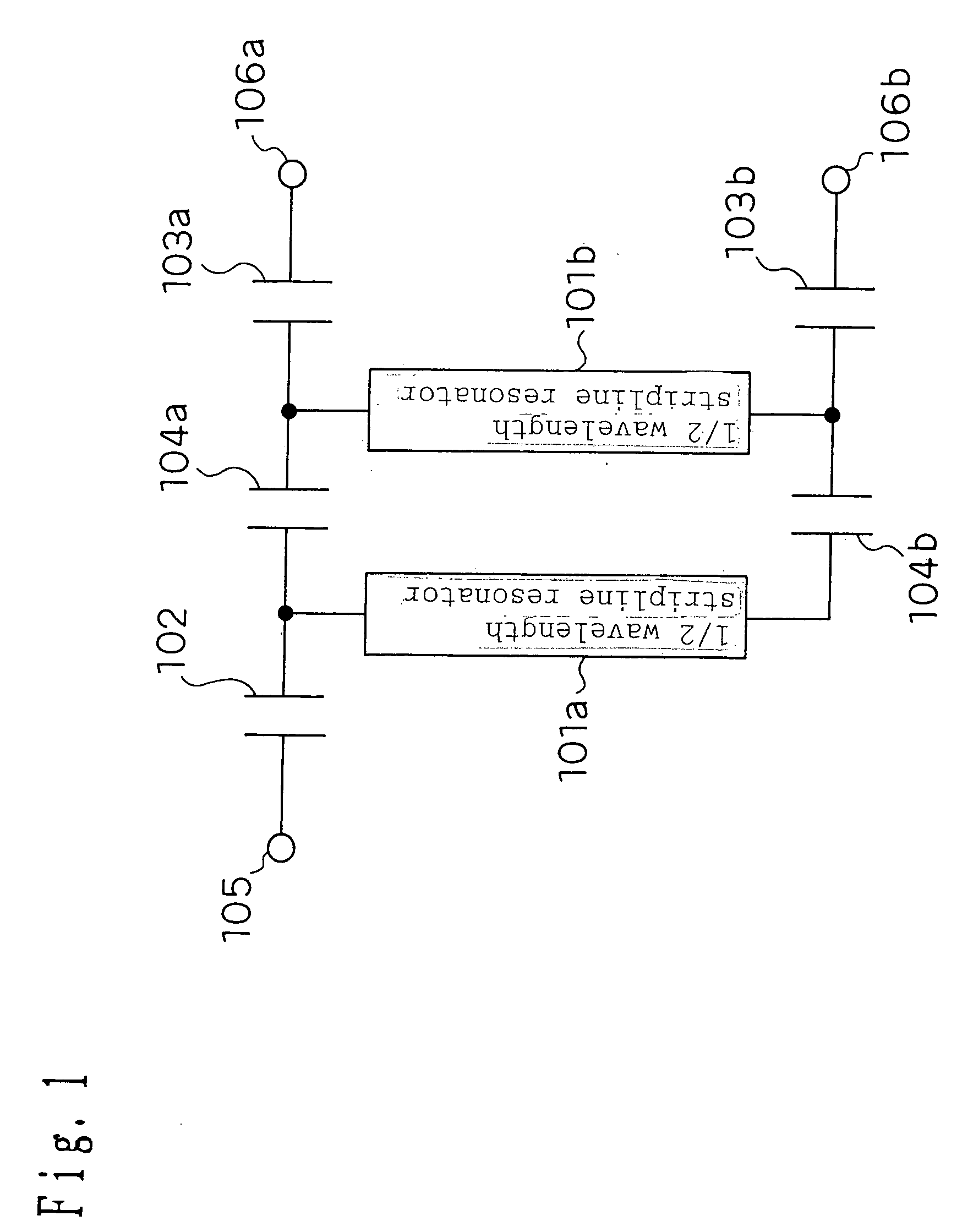
[0223] FIG. 1 is one of equivalent circuit diagrams of a band-pass filter of an unbalanced input (output)-balanced output (input) type according to a first embodiment of the present invention.

[0224] According to this configuration, stripline resonators 101a and 101b are placed, and they are electromagnetically coupled. The stripline resonators 101a and 101b substantially have the length of 1 / 2 wavelength (electrical length, same hereafter) of desired resonant frequencies. One end of the stripline resonator 101a is connected to an unbalanced input (output) terminal 105 via a coupling capacitance 102, and both ends of the stripline resonator 101b are connected to balanced output (input) terminals 106a and 106b via coupling capacitances 103a and 103b. Furthermore, two inter-section coupling capacitances 104a and 104b are connected between both ends of the stripline resonators 101a and 101b.

[0225] Next, an operation of the band-pass filter shown in FIG. 1 will b...

second embodiment

[0236] (Second Embodiment)

[0237] Next, FIG. 5(a) shows an equivalent circuit configuration of the band-pass filter of the unbalanced input (output)-balanced output (input) type for controlling the frequency of the attenuation pole according to the second embodiment of the present invention.

[0238] As shown in FIG. 5(a), this is the configuration wherein, as to the equivalent circuit configuration of the unbalanced-balanced laminated filter in FIG. 1, the inter-section coupling capacitance 104a as an example of a first capacity element of the present invention and the inter-section coupling capacitance 104b as an example of a second capacity element are placed at distances L1 and L2 in a central direction from both ends of the pair of stripline resonators 101a and 101b of substantial 1 / 2 wavelength of the resonant frequencies respectively. It is possible to realize the laminated structure for implementing this equivalent circuit by changing coupling positions of the inter-section coup...

third embodiment

[0250] (Third Embodiment)

[0251] FIG. 8 is an equivalent circuit diagram of the unbalanced-balanced band-pass filter according to a third embodiment of the present invention.

[0252] According to this configuration, there are one stripline resonator 801a of substantial 1 / 2 wavelength of the desired resonant frequencies and a pair of stripline resonators 821a and 821b of substantial 1 / 4 wavelength of the desired resonant frequencies. The stripline resonators 821a and 821b are placed in parallel with the stripline resonator 801a and mutually in series in order to be electromagnetically coupled respectively. One end of the stripline resonator 801a is connected to an unbalanced input (output) terminal 805 via a coupling capacitance 802. Ends of the respective stripline resonators 821a and 821b are connected to balanced output (input) terminals 806a and 806b via coupling capacitances 803a and 803b, and the other ends of the respective stripline resonators 821a and 821b form the short circui...


PUM


Abstract

A filter having an unbalanced terminal, a first stripline resonator of which one end is connected to the unbalanced terminal, a second stripline resonator placed to be electromagnetically coupled to the first stripline resonator, and balanced terminals and of which both ends are connected to the second stripline resonator, wherein the first stripline resonator and the second stripline resonator are connected by at least one impedance element, and the second stripline resonator is a ½ wavelength resonator substantially having ½ length of a wavelength of a resonance frequency.

Description

[0001] 1. Field of the Invention[0002] The present invention relates to a filter for rendering input-output as unbalanced input (output)-balanced output (input) used for a high-frequency circuit of wireless applications and so on, and a high-frequency module, a communication device and a filtering method utilizing it.[0003] 2. Related Art of the Invention[0004] In recent years, small-sized and high-performance filters are in increasing demand as the communication devices are miniaturized. To realize them, ceramic laminated filters suited to smaller sizes and lower profiles are increasingly used.[0005] An equivalent circuit of a laminated band-pass filter (BPF) of an unbalanced input-output type as one of the laminated filters is constituted as in FIG. 18.[0006] According to this configuration, two stripline resonators 181a and 181b substantially having the length of 1 / 4 wavelength (electrical length) of resonant frequencies for mutually electromagnetic coupling are placed by shortin...

Claims


Application Information

Patent Timeline
Patent Type & Authority Applications(United States)
IPC IPC(8): H01P1/203
CPCH01P1/20345
Inventor IWASAKI, TOMOHIRONAKAMURA, HIROYUKIISHIZAKI, TOSHIOURIU, KAZUHIDE
Owner PANASONIC CORP
Why Eureka
Try Eureka