Eureka AIR delivers breakthrough ideas for toughest innovation challenges, trusted by R&D personnel around the world.

Portable pressure relief system & methods

a pressure relief system and portability technology, applied in the field of portability pressure relief system & methods, can solve the problems of reducing patient mobility, reducing patient mobility, and reducing patient mobility, so as to reduce costs, enhance patient mobility, and enhance patient mobility

Inactive Publication Date: 2004-05-27
AHMED A MATEEN
View PDF17 Cites 35 Cited by
  • Summary
  • Abstract
  • Description
  • Claims
  • Application Information

AI Technical Summary

Benefits of technology

[0004] This invention, with its several desirable features, is summarized in the CLAIMS that follow. After reading the following section entitled "DETAILED DESCRIPTION OF SOME EMBODIMENTS OF THIS INVENTION," one will understand how the features of this invention provide its benefits. The benefits of this invention include, but are not limited to: reduced costs associated with care giving for patients requiring drainage of fluids, convenience of use and enhanced mobility of for patients requiring drainage of fluids, avoidance of catheter blockage, and enhanced patient mobility.
[0010] In this one embodiment, a connector adapted to be attached to the cranium holds the first end of the catheter in position in the cavity. This connector is also a feature of this invention, preventing leakage of fluid past it, so that essentially all the fluid flowing from the cavity passes through the catheter with essentially no fluid bypassing the catheter and flowing around the connector. The outlet of the pressure-responsive valve is attached so as to receive the fluid. The connector may be integral with the catheter and may include a thread element on an external surface of the catheter at or nearby the outlet end of the catheter. The connector fits snugly into a hole in the cranium to prevent any substantial leakage of fluid past the connector, and it may have a passageway therein through which the drainage catheter extends so that the outlet end of the catheter is external to the cranium. The passageway may be formed by a substantially cylindrical wall member with a cleft therein. Typically, the connector may have a body with external threads thereon enabling the connector to be screwed into the hole. This body is made of a material that deforms upon compression and has a substantially truncated conical shape sized to fit into the hole and compress as the connector is screwed to the hole. Such a connector provides a substantially fluid tight seal between the hole and the body, with the passageway being constricted as connector is screwed into the hole to provide a substantially fluid tight seal between the catheter and the passageway. In one embodiment, the body may have an enlarged head that acts as a stop adapted to bear against an external portion of the cranium surrounding the hole. The enlarged head may have at least one suture orifice therein to enable the connector to be sutured to the cranium to prevent movement of the connector within the hole after insertion into the hole.
[0014] One method is specific for collecting fluid within a cavity formed at least in part by the ventricle walls of the brain enclosed within the cranium of a patient. A hole is formed in the cranium to provide access to the cavity and a plug-type connector sized to fit snugly in the hole to prevent any substantial leakage of fluid past the connector. The connector may have a passageway therein. An elongated drainage catheter passes through the passageway so that a first end of the catheter is seated within the cavity and a second end of the catheter is external to the cranium. The first end may have at least one drainage aperture therein. Typically, the drainage catheter fits snug within the passageway to prevent any substantial leakage of between the catheter and the passageway. The flow of fluid from the cavity is controlled so that the fluid pressure within cavity is maintained at a level that prevents the ventricle walls form making substantial contact with the drainage apertures. In one embodiment, a connector is used of the type discussed above.

Problems solved by technology

An incorrect pressure differential results either in too much fluid drainage or inadequate drainage.
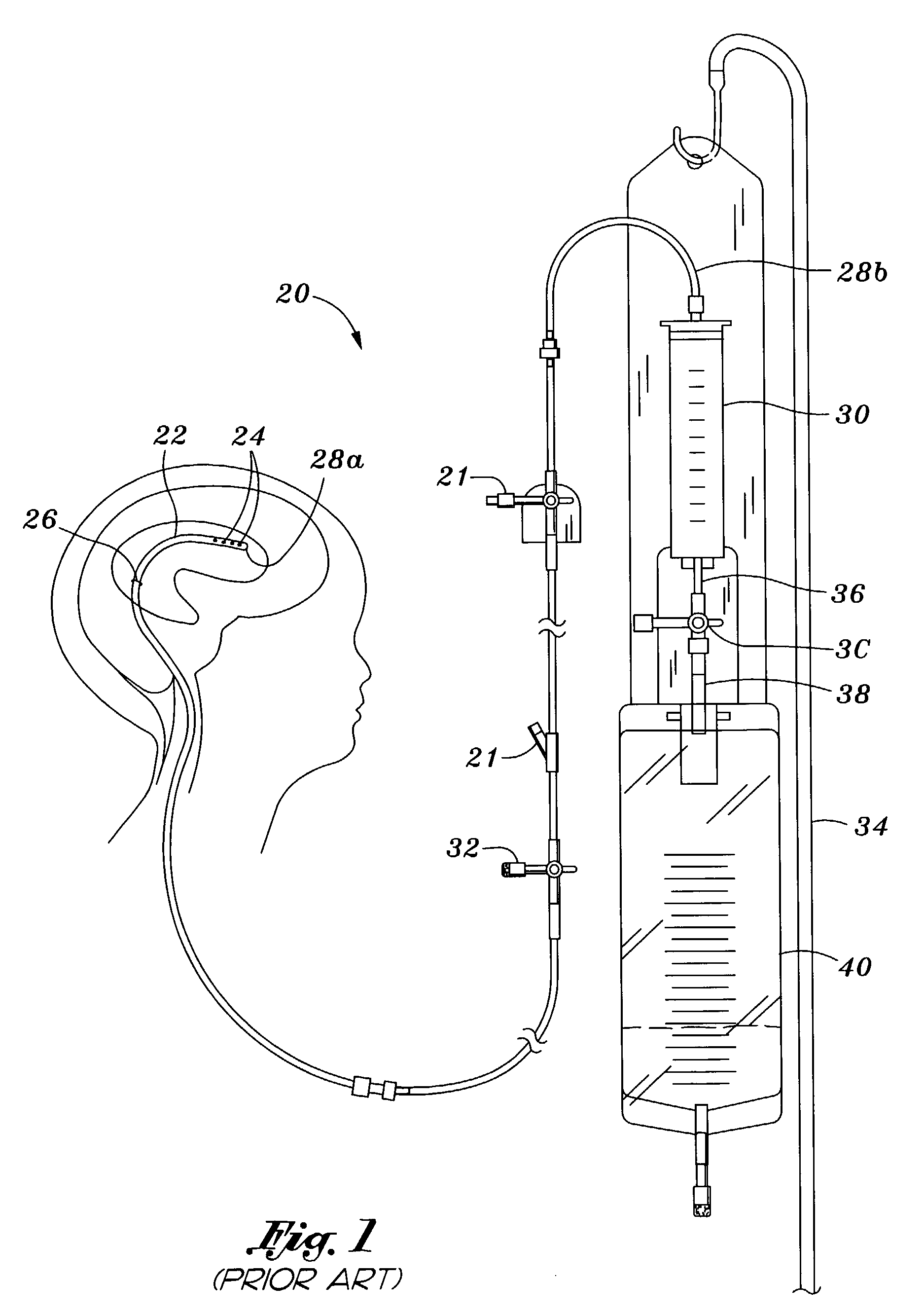
The system 20 illustrated in FIG. 1 is relatively cumbersome and essentially relegates the patient to the hospital bed.
Moreover, movement of the patient changes the relative elevation of the proximal and distal ends of catheter, and thus alters the pressure differential therethrough.
This prior art system is both cumbersome, inconvenient to the patient, and requires a nurse to spend time attending to the patient.

Method used


Image

  • Portable pressure relief system & methods
  • Portable pressure relief system & methods
  • Portable pressure relief system & methods

Examples


Embodiment Construction

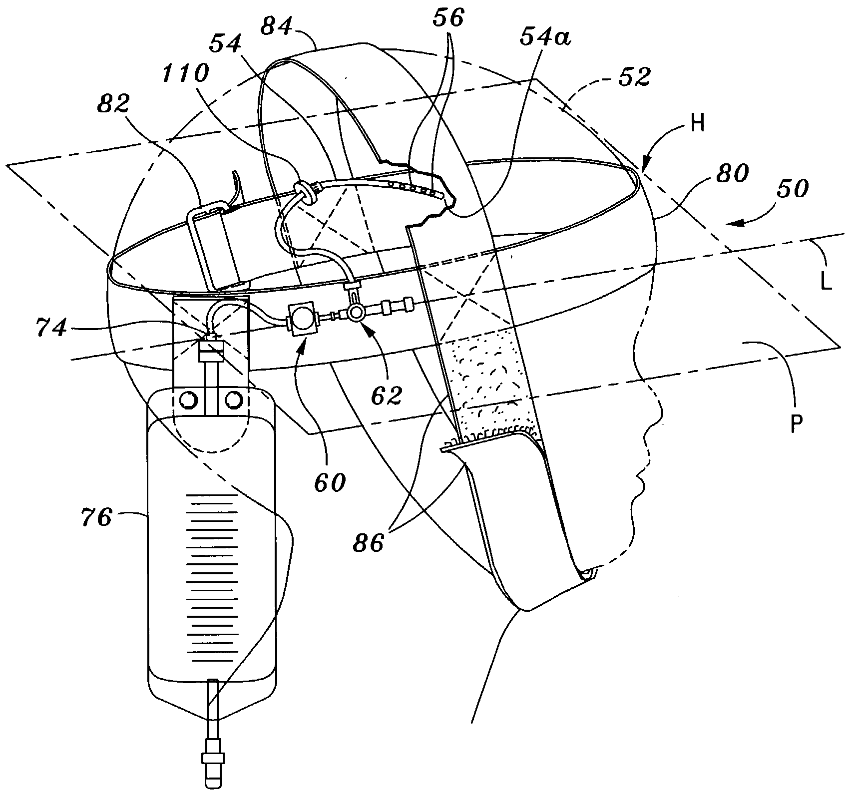
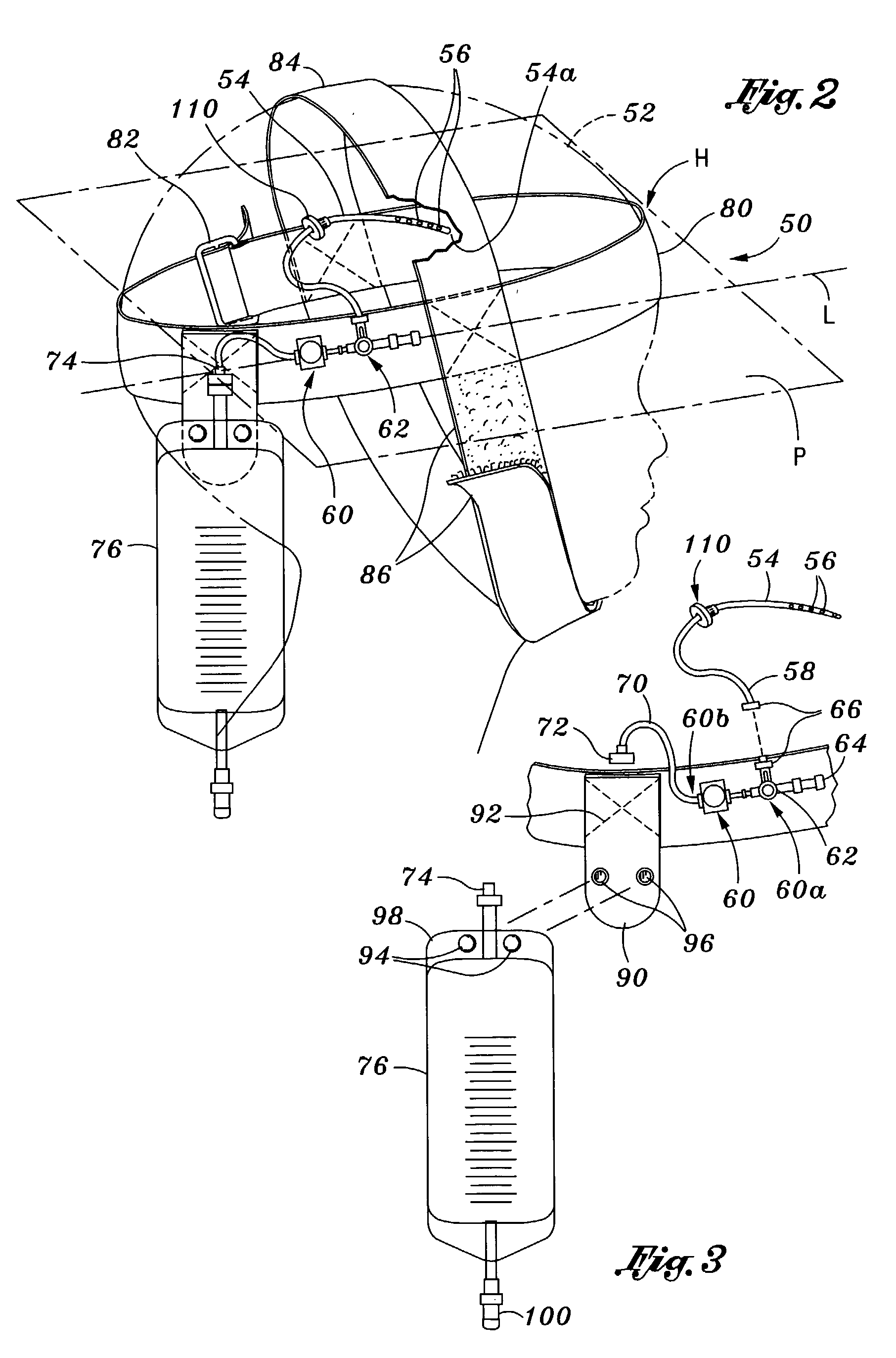
[0037] One embodiment of the intracranial drainage system 50 of present invention is shown in FIG. 2 mounted to the head 52 of a patient. FIG. 3 shows this system 50 in isolation and partially exploded. The drainage system 50 comprises a drainage catheter 54 having a distal end 54a with a plurality of drainage apertures 56 therein. A proximal end 58 of the drainage catheter 54 is in fluid communication with an inlet 60a of a one-way pressure-responsive valve 60. The proximal end 58 may connect directly to the inlet 60a of the pressure-responsive valve 60, or may be connected via an intermediate three-way junction or stock cock 62 having a sampling port 64. A mating pair of connectors 66 may be utilized so that the drainage catheter 54 can be decoupled from the remainder of the system if necessary.

[0038] A drainage tube 70 attaches to an outlet 60b of the pressure-responsive valve 60 and has a coupling 72 on its opposite end that mates with an inlet to 74 of a reservoir bag 76. The s...


PUM


Abstract

A portable systems release fluid pressure with a cavity within a patient. These systems include a drainage catheter, a pressure-responsive one-way valve, and a fluid reservoir all adapted to be mounted in proximity to the cavity being drained. One system in particular is used in relieving intracranial pressure. This intracranial pressure relief system may include a headband to which are mounted the one-way valve and reservoir. The drainage catheter may have mounted thereon a cranium seal formed of a soft material that contacts the inner wall of a cranium bore hole. The cranium seal may have threads to facilitate advancement into the bore hole.

Description

INCORPORATION BY REFERENCE[0001] Applicant incorporates herein by reference any and all U.S. patents, U.S. patent applications, and other documents cited or referred to in this application or cited or referred to in the U.S. patents and U.S. patent applications incorporated herein by reference.DEFINITIONS[0002] The words "comprising," "having," and "including," and other forms thereof, are intended to be equivalent in meaning and be open ended in that an item or items following any one of these words is not meant to be an exhaustive listing of such item or items, or meant to be limited to only the listed item or items.BACKGROUND OF INVENTION[0003] Frequently it is necessary to drain fluids, particularly liquids, from various cavities in the body. For example, hydrocephalus arises when the outflow of cerebrospinal fluid (CSF) is obstructed, which collects in the ventricles of the brain and produces an increase in the intracranial pressure. Left untreated, hydrocephalus can result in ...

Claims


Application Information

Patent Timeline
IPC IPC(8): A61M27/00
CPCA61M2202/0464A61M27/006
Inventor AHMED, A. MATEEN
Owner AHMED A MATEEN
Why Eureka
Eureka Blog
Learn More