Force-indicating strap fastener

a technology of straps and fasteners, applied in the direction of wire tools, transportation items, manufacturing tools, etc., can solve the problems of strap fracture, strap tensile force may be too large for the strap to sustain, and article loosening,

Inactive Publication Date: 2004-06-03
HUANG HAN CHING
View PDF2 Cites 31 Cited by
  • Summary
  • Abstract
  • Description
  • Claims
  • Application Information

AI Technical Summary

Benefits of technology

0007] According to the present invention, a force-indicating strap fastener includes a base, an axle, a lever, two ratchet wheels, a first detent, a second detent, and a force gauge. The base including a first guiding element formed thereon and a second guiding element formed thereon. The axle is rotationally mounted on the base. The lever is pivotally mounted on the axle. The ratchet wheels are secured to the axle. The first detent is mounted on the base for engagement with the ratchet wheels. Thus, rotation of the axle relative to the base in a first direction is allowed, but rotation of the axle in a second direction opposite to the first direction is avoided. The second detent is mounted on the lever for engagement with the ratchet wheels. Thus, pivoting of the lever in the first direction results in rotation of the axle in the first direction, but pivoting of the lever in the second direction does not entail rotation of the axle in the second direction. The force gauge includes a casing, a spring, an anvil and an indicator. The casing is mounted on the base and formed with a scale. The spring is received in the casing. The anvil includes a first end in contact with the spring and a second end outside the casing. The indicator is connected with the anvil for pointing at a value in the scale depending on the tensile force.

Problems solved by technology

If the tensile force is too small to restrict the article, the article will get loose and become vulnerable to damages.
However, the tensile force may be too large for the strap to sustain.
In such a case, the strap may be fractured.
When that happens, the at least one article will get loose and become vulnerable to damages.
What is worse is that the loose article may cause severe damages to people.

Method used


Image

  • Force-indicating strap fastener
  • Force-indicating strap fastener
  • Force-indicating strap fastener

Examples


Embodiment Construction

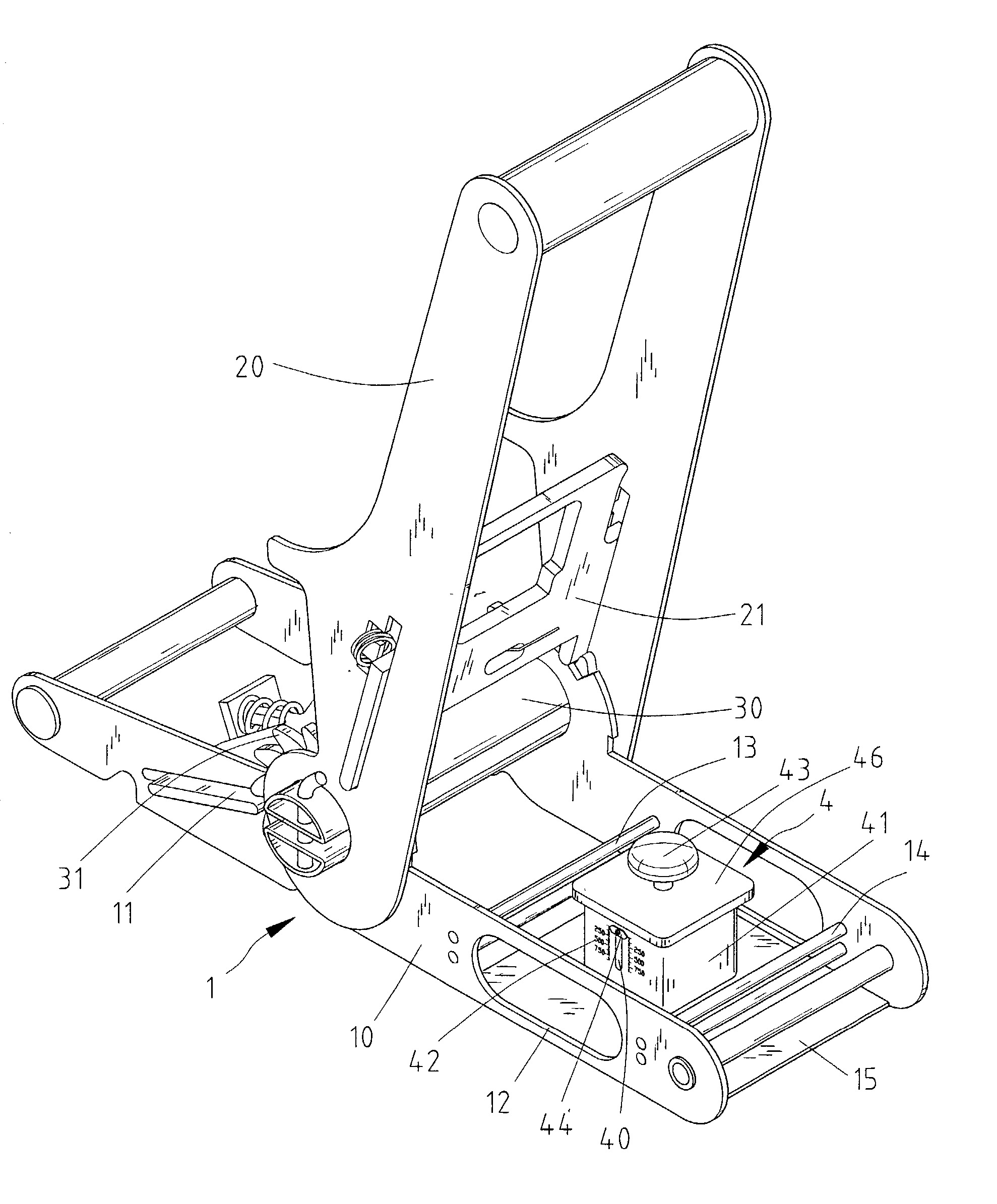
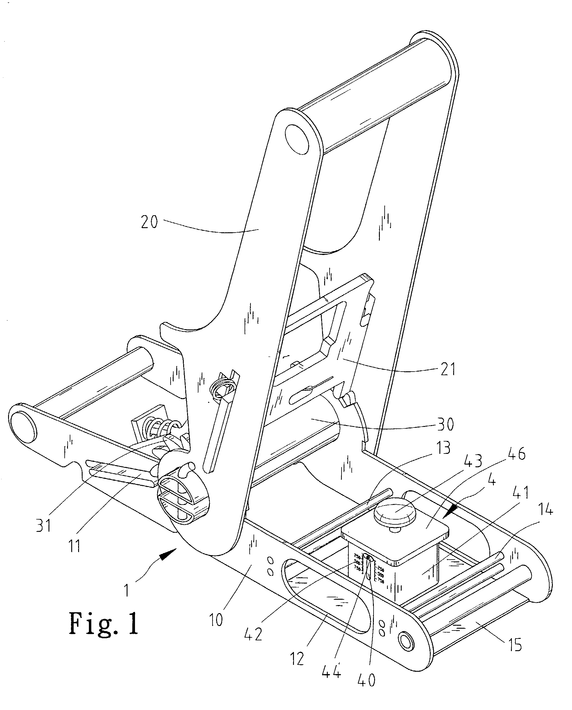
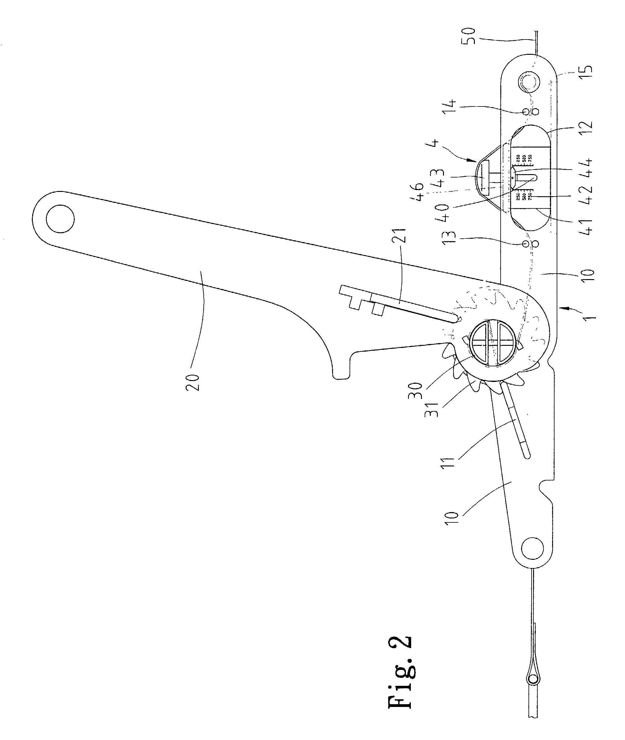
[0015] Referring to FIGS. 1.about.5, a strap fastener 1 is equipped with a force gauge 4 according to the preferred embodiment of the present invention. The strap fastener 1 includes a base 10, a lever 20, an axle 30, two ratchet wheels 31, a first detent 11 and a second detent 21.

[0016] The base 10 includes two side elements. One of the side elements of the base 10 defines a window 12. A first pair of guiding elements 13 is formed between the side elements of the base 10. A second pair of guiding elements 14 is formed between the side elements of the base 10. A platform 15 is formed between the side elements of the base 10.

[0017] The axle 30 is rotationally mounted on the base 10. The ratchet wheels 31 are secured to the axle 30. The first detent 11 is biased by a spring. The first detent 11 is mounted on the base 10 for engagement with the ratchet wheels 31. Thus, rotation of the axle 30 relative to the base 10 in a first direction is allowed, but rotation of the axle 30 in a seco...


PUM

PropertyMeasurementUnit
forceaaaaaaaaaa
tensile forceaaaaaaaaaa

Abstract

A force-indicating strap fastener includes a base, an axle, a lever, two ratchet wheels, a first detent, a second detent, and a force gauge. The base including a first guiding element formed thereon and a second guiding element formed thereon. The axle is rotationally mounted on the base. The lever is pivotally mounted on the axle. The ratchet wheels are secured to the axle. The first detent is mounted on the base for engagement with the ratchet wheels. Thus, rotation of the axle relative to the base in a first direction is allowed, but rotation of the axle in a second direction opposite to the first direction is avoided. The second detent is mounted on the lever for engagement with the ratchet wheels. Thus, pivoting of the lever in the first direction results in rotation of the axle in the first direction, but pivoting of the lever in the second direction does not entail rotation of the axle in the second direction. The force gauge includes a casing, a spring, an anvil and an indicator. The casing is mounted on the base and formed with a scale. The spring is received in the casing. The anvil includes a first end in contact with the spring and a second end outside the casing. The indicator is connected with the anvil for pointing at a value in the scale depending on the tensile force.

Description

BACKGROUND OF INVENTION[0001] 1. Field of Invention[0002] The present invention relates to a force-indicating strap fastener.[0003] 2. Related Prior Art[0004] Taiwanese Patent Publication No. 383756 discloses a conventional strap fastener. This conventional strap fastener is used to fasten a strap wrapped around an article. This conventional strap exerts a tensile force on the strap that in turn exerts a force on the article. If the tensile force is too small to restrict the article, the article will get loose and become vulnerable to damages. However, the tensile force may be too large for the strap to sustain. In such a case, the strap may be fractured. When that happens, the at least one article will get loose and become vulnerable to damages. What is worse is that the loose article may cause severe damages to people.[0005] The present invention is therefore intended to obviate or at least alleviate the problems encountered in prior art.SUMMARY OF INVENTION[0006] It is the primar...

Claims


Application Information

Patent Timeline
Patent Type & Authority Applications(United States)
IPC IPC(8): A44B11/12B60P7/08
CPCA44B11/125Y10T24/21B60P7/0861
Inventor HUANG, HAN-CHING
Owner HUANG HAN CHING
Why Eureka
Try Eureka