Constant velocity coupling and control system therefor

a constant velocity coupling and control system technology, applied in the direction of yielding couplings, couplings, rotary machine parts, etc., can solve the problems of vehicles not being able to maintain a strict geometric relationship, the angular velocity of the output shaft fluctuating sinusoidally, etc., to facilitate the use of a member and facilitate the operation of the centering mechanism.

Inactive Publication Date: 2004-06-03
THOMPSON COUPLINGS
View PDF10 Cites 12 Cited by
  • Summary
  • Abstract
  • Description
  • Claims
  • Application Information

AI Technical Summary

Benefits of technology

[0080] Clearly all relative movements of components within the coupling are rotational and are realized by roller bearings, thus largely eliminating torque losses through friction.
[0175] The assembly disclosed herein facilitates the use of a member as depicted in FIG. 17.8. The member depicted in FIG. 17.8 is a shaft member adapted to connect to the center of the joint as either an input shaft or output shaft in place of one of the yoke members. So as to facilitate operation of the centering mechanism as disclosed herein the member shown in FIG. 17.8 has an arcuate slot 36 formed therein so as to permit ring members 21 and 26 to pass through and within the said arcuate slot there is provided a pin 37 so as to perform the same task as pin 19 or 20 as the case may be. FIG. 17.9 is a depiction of the linkage mechanism disclosed in the eleventh embodiment. It will be observed that the centering means disclosed herein together with the member depicted in FIG. 17.8 is particularly applicable as a suitable centering means for a constant velocity joint utilizing the linkage means depicted in FIG. 17.9. In such an application bearing 22 and 23 would be located by pins 38 and 39 respectively.

Problems solved by technology

An inherent flaw in the design of the simple Cardan Joint is the fact that at any angle between input and output shafts other than 180 degrees, the angular velocity of the output shaft fluctuates sinusoidally relative to that of the input shaft.
As well it is impossible in many applications and in particular in road vehicles to maintain a strict geometric relationship between input and output shafts giving rise to vibrations, mechanical stresses and power transmission losses.
The major shortcomings of this arrangement reside in the transfer of any axial and radial loads to the centering mechanism resulting in accelerated wear and frictional losses.
Generally all suffer from being approximate solutions to the strict geometrical constraints of a true constant velocity coupling or achieve an approximation to the geometry at the cost of high wear frictional losses from sliding components.

Method used


Image

  • Constant velocity coupling and control system therefor
  • Constant velocity coupling and control system therefor
  • Constant velocity coupling and control system therefor

Examples


first embodiment

[0225] First Embodiment

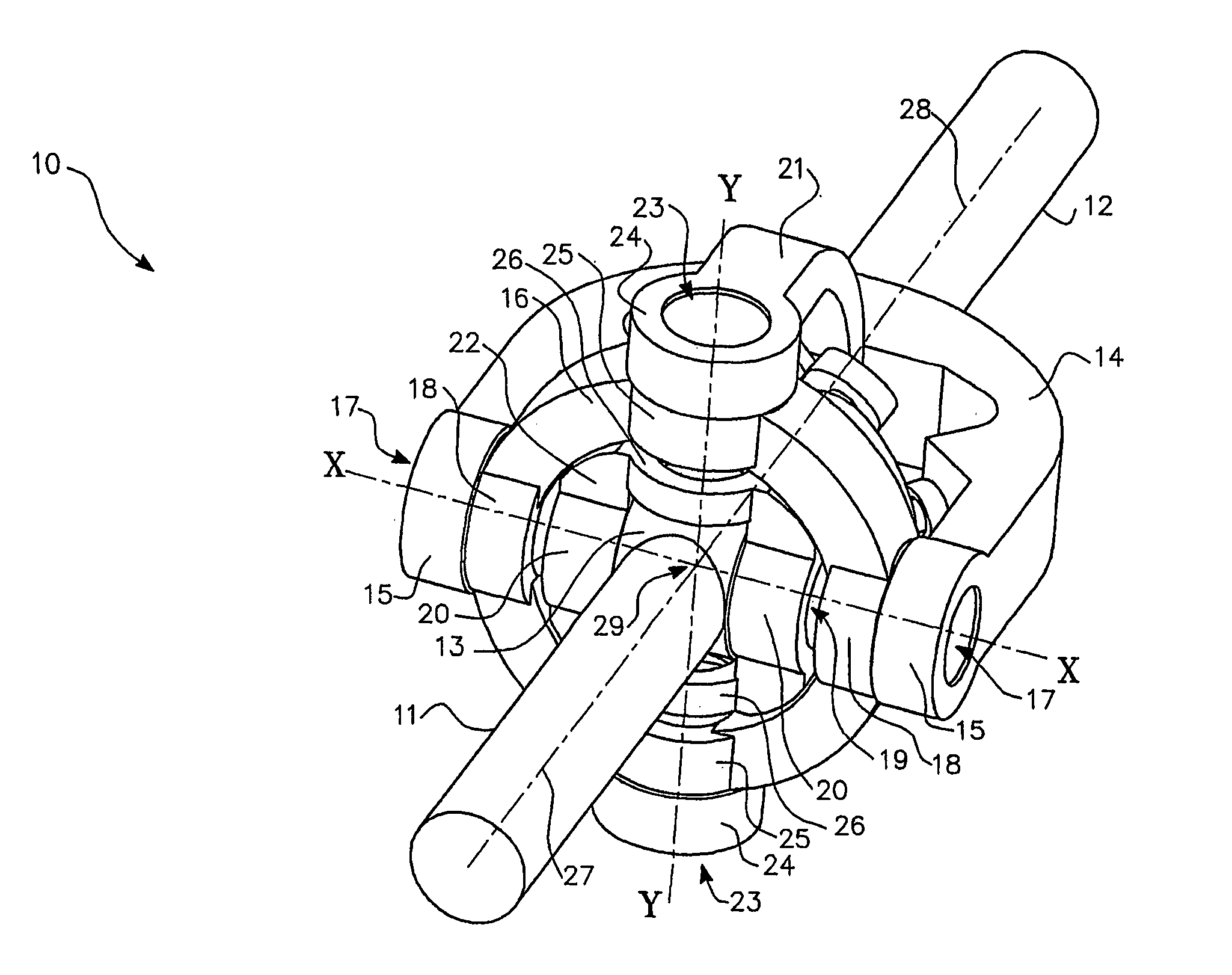
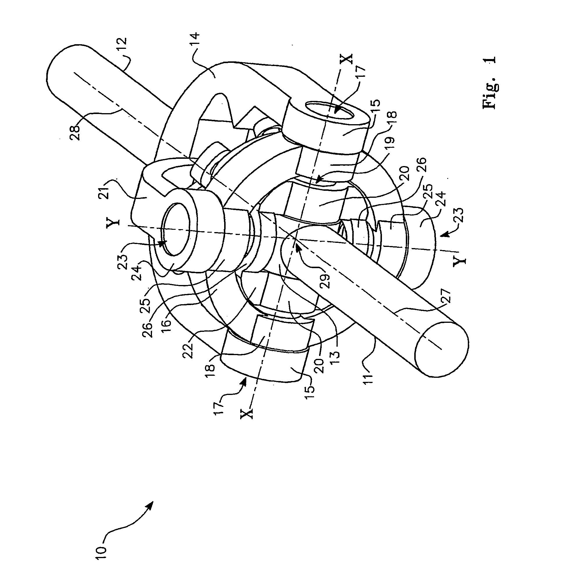
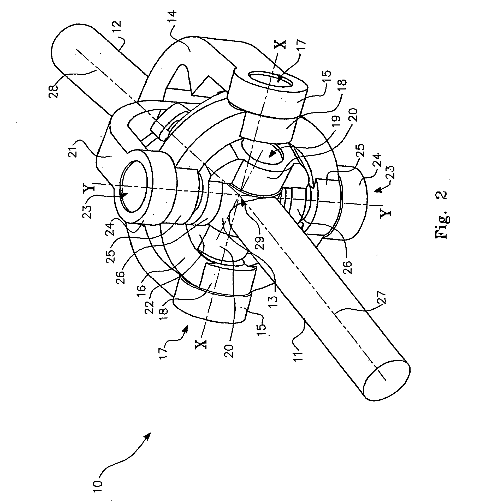
[0226] A constant velocity coupling wherein the axes of all rotational elements intersect at the intersection of the input and output shaft axes. The coupling is provided with a control yoke and control mechanism wherein the control yoke defines an axis of rotation bisecting the supplementary angle between the input shaft axis and output shaft axis of the coupling.

[0227] The control mechanism is in the form of a double scissor assembly where all linkages have axes radial to the intersection point of the input and output shaft axes, the pivoting centers of the control linkages effectively lying at the vertices of equal spherical triangles.

second embodiment

[0228] Second Embodiment

[0229] A constant velocity coupling wherein all elements are identical to those of the first embodiment except that the control mechanism consists of a geared mechanism where two linkage arms provided with gear segments mesh with a central gear, this assembly controlling the axis of the control yoke to lie on the bisector of the supplementary angle between the input and output shaft axes.

third embodiment

[0230] Third Embodiment

[0231] A constant velocity coupling wherein either the scissor mechanism of the first embodiment, or the geared mechanism of the second embodiment controlling the axis of the control yoke to lie on the bisector of the supplementary angle between the input and output shaft axes but where the inner and outer yokes are modified from a full circular form to a partial segment form.


PUM


Abstract

A constant velocity coupling 10, 305 which rotatably connects an input shaft 11 to an output shaft 12 by means of a control mechanism or control system 21, 309 which, in particular forms, includes a gimbal arrangement comprised of an inner yoke 22 rotatably connected to an outer yoke 16. The control mechanism including control yoke 21 constrains at least portions of the coupling to lie on or in association with a homokinetic plane 300 of the coupling. In particular forms the control mechanism operates symmetrically about supplementary angle bisector 308.

Description

[0001] The present invention relates to couplings between shafts and in particular forms to universal joints and, more particularly to couplings having or seeking to achieve equal instantaneous input shaft and output shaft angular velocities.[0002] The problem of coupling two rotating shafts operating at an angle to each other has confronted engineers since at least the beginning of the industrial revolution. The "Cardan Joint" developed initially by Cardan in the 16.sup.th century is in principle still in use today despite its inherent shortcomings and is found for example in virtually every rear wheel drive vehicle.[0003] An inherent flaw in the design of the simple Cardan Joint is the fact that at any angle between input and output shafts other than 180 degrees, the angular velocity of the output shaft fluctuates sinusoidally relative to that of the input shaft.[0004] Commonly, and as employed again for example in the drive lines of rear wheel drive vehicles, two Cardan Joints ar...

Claims


Application Information

Patent Timeline
Patent Type & Authority Applications(United States)
IPC IPC(8): F16D3/30
CPCF16D3/30Y10S464/904Y10S464/905
Inventor THOMPSON, GLENN ALEXANDER
Owner THOMPSON COUPLINGS
Why Eureka
Try Eureka