
High pressure oil pump roller tappet

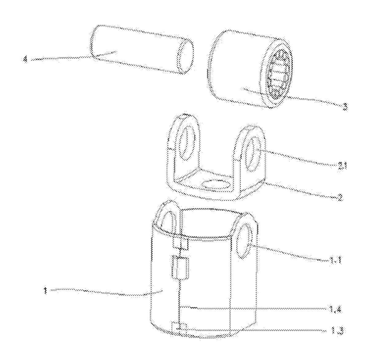
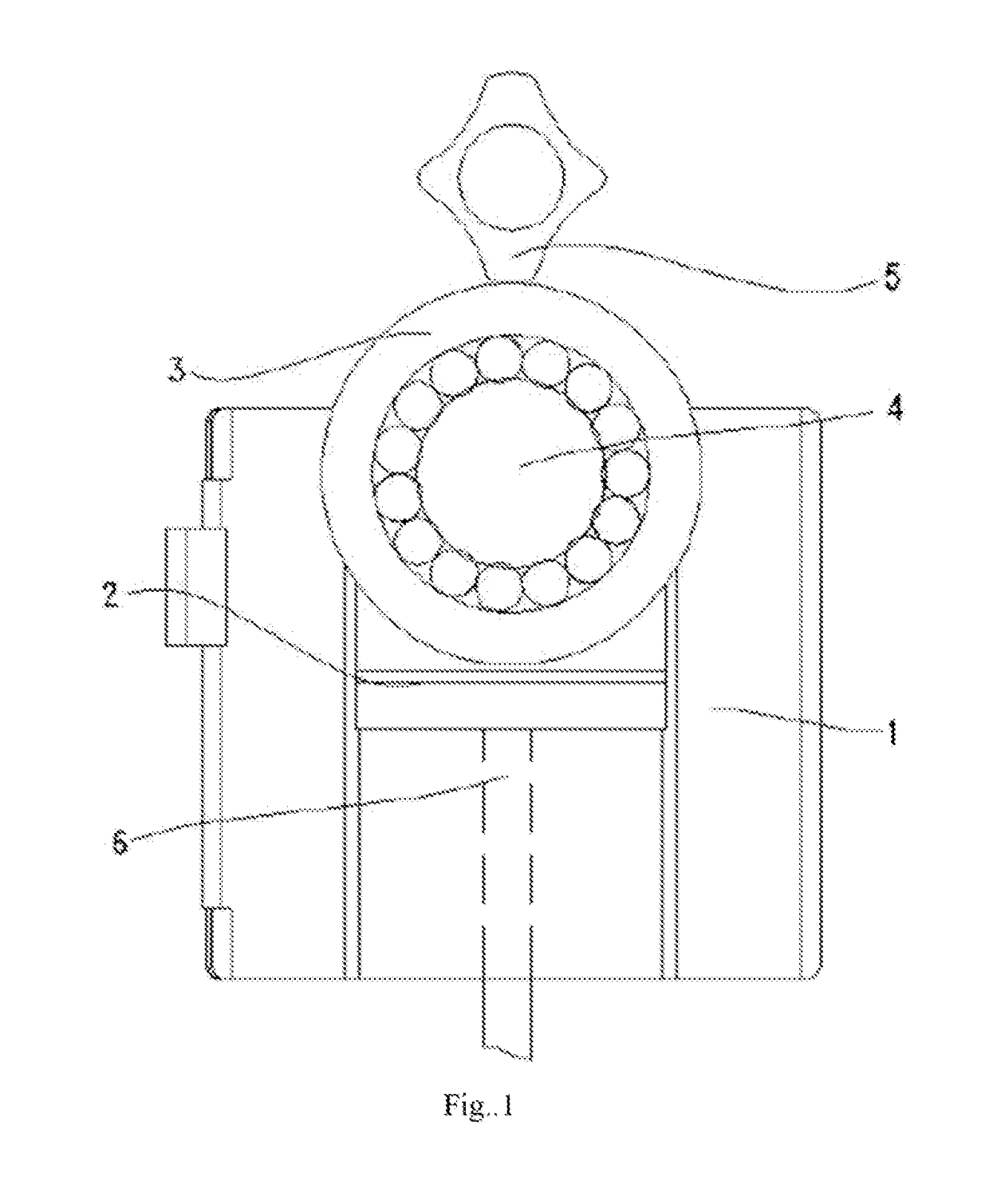
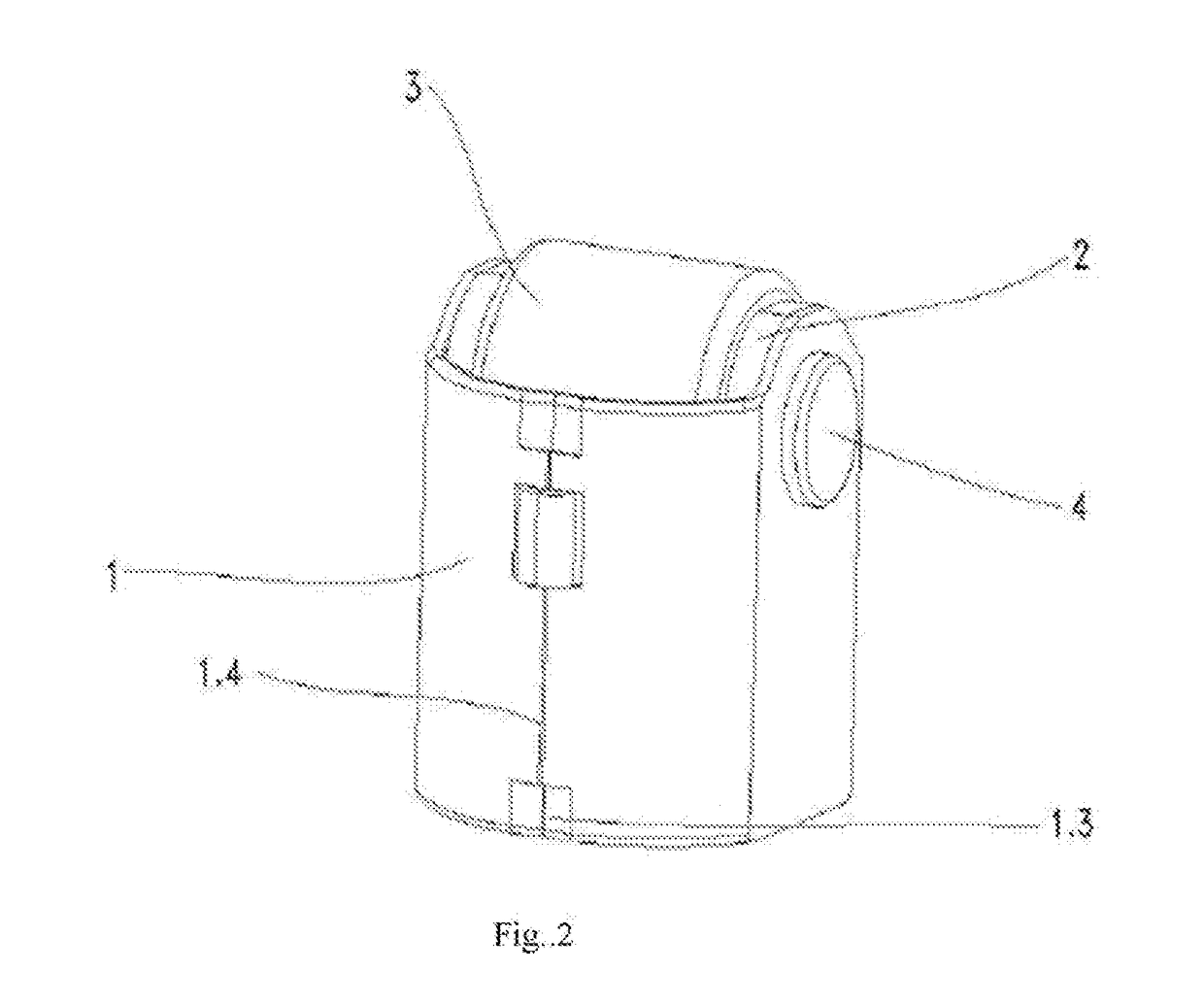
a high-pressure oil pump and roller technology, which is applied in the direction of machines/engines, fuel injecting pumps, positive displacement liquid engines, etc., can solve the problems of vibration of the shell inside the cylinder, difficult to reduce weight and cost, and complex and costly problems, so as to achieve easy structure and assembly process, cost and weight control

Inactive Publication Date: 2017-11-30
HANGZHOU XZB TECH
View PDF1 Cites 6 Cited by
  • Summary
  • Abstract
  • Description
  • Claims
  • Application Information

AI Technical Summary

Benefits of technology

The patent describes a new design for an engine that reduces vibration, abrasion, and weight. The engine is designed with a separate shell and holder, which reduces the likelihood of vibration. The bottom of the holder can also be designed to create less friction. The locking block used to limit the axial rotation of the roller tappet is designed as integral with the shell, improving efficiency and reducing cost. The holder is also of a U-shaped structure, reducing mass and increasing stiffness. A pin is designed to transmit force from the driving cam effectively, reducing lateral force on the shell. Overall, the design improves engine performance and reliability.

Problems solved by technology

The existing shell of the high pressure oil pump roller tappet is made by integrated forging process, which is complex and costly, and has a certain requirement on the thickness of the plate during stamping.
As a result, it is difficult to reduce weight and the cost.
As a result, the lateral force acting on the holder from the driving cam will be transmitted to the shell, causing the vibration of the shell inside the cylinder.
Accordingly, damages to the cylinder and the shell are likely to be caused.
Its manufacture process is complex.

Method used


Image

  • High pressure oil pump roller tappet
  • High pressure oil pump roller tappet
  • High pressure oil pump roller tappet

Examples


embodiment 3

[0056]As shown in FIG. 10 and FIG. 11, the baseplate of the holder 2 is the baseplate I 2.2 which has a projecting curved structure. A groove 2.4 is arranged on the underside of the baseplate I 2.2. A boss 2.5 is formed on the upper side of the baseplate I 2.2 accordingly.

embodiment 4

[0057]As shown in FIG. 12 and FIG. 13, the baseplate of the holder 2 is the baseplate II 2.3 which has a planar structure. A groove 2.4 is arranged on the underside of the baseplate II 2.3. A boss 2.5 is formed on the upper side of the baseplate II 2.3 accordingly.

embodiment 5

[0058]As shown in FIG. 14, the baseplate of the holder 2 is the baseplate II 2.3 which has a planar structure. The difference with respect to Embodiment 2 lies in that a plurality of the ribs 2.6 are arranged on bending parts between the vertical plates and the baseplate of the holder 2.

[0059]Obviously, the structure of the rib 2.6 in Embodiment 5 of the holder 2 can also be applied to Embodiment 1, Embodiment 3, and Embodiment 4.

[0060]Among them, variations of the pin 4 include:


PUM


Abstract

A high-pressure oil pump roller tappet, used for automobile fuel injection system, mounted between the driving cam and the tappet. The roller tappet includes a shell, a holder, a roller, and a pin. Planes A are arranged on both sides of the seam on lateral sides of the shell. Holes I are arranged at symmetrical positions on two planes A. Holes II are arranged on symmetrical positions on vertical plates. The roller is located in the middle of the pin. Welding has no requirement on the thickness of the plate. The weight can be controlled effectively, reducing inertia force, friction, and wear, improving engine efficiency. The shell and holder are designed as being separate, ensuring that the shell subjects to lateral force as little as possible when the holder subjects to a force, such that the shell is less likely to vibrate. Thus, the shell avoids the abrasion.

Description

TECHNICAL FIELD[0001]The invention relates to the technical field of engine equipment, especially to a high pressure oil pump roller tappet.BACKGROUND[0002]The roller tappet is an important part of the automobile engine using high-pressure oil pump system, and is mounted between the driving cam and the tappet to transform the rotational motion of the driving cam into the linear reciprocating motion of the tappet. The main structure of the roller tappet includes a shell, a holder, a roller and a pin.[0003]The existing shell of the high pressure oil pump roller tappet is made by integrated forging process, which is complex and costly, and has a certain requirement on the thickness of the plate during stamping. As a result, it is difficult to reduce weight and the cost. The shell may be forged integrally with the holder. Alternatively, the holder may be directly arranged on the shell. As a result, the lateral force acting on the holder from the driving cam will be transmitted to the sh...

Claims


Application Information

Patent Timeline
Patent Type & Authority Applications(United States)
IPC IPC(8): F02M59/10F01L1/46
CPCF02M59/102F01L1/46F01L2105/00F01L2105/02F01L1/14F01L1/245F01L2109/00F04B1/0426F01L2305/00F01L2305/02F01L2309/00
Inventor XU, NAREN, HAIJUN
Owner HANGZHOU XZB TECH
Learn More