Friction agitation joining tool, friction agitation joining method and joined member manufacturing method

a technology of friction agitation and joining tool, which is applied in the direction of manufacturing tools, soldering devices,auxillary welding devices, etc., can solve the problems of difficult joining operation and difficulty in performing joining operation, and achieve good joining condition and prevent the effect of decreasing the thickness of the joined portion

Inactive Publication Date: 2004-06-10
SHOWA DENKO KK
View PDF4 Cites 31 Cited by
  • Summary
  • Abstract
  • Description
  • Claims
  • Application Information

AI Technical Summary

Benefits of technology

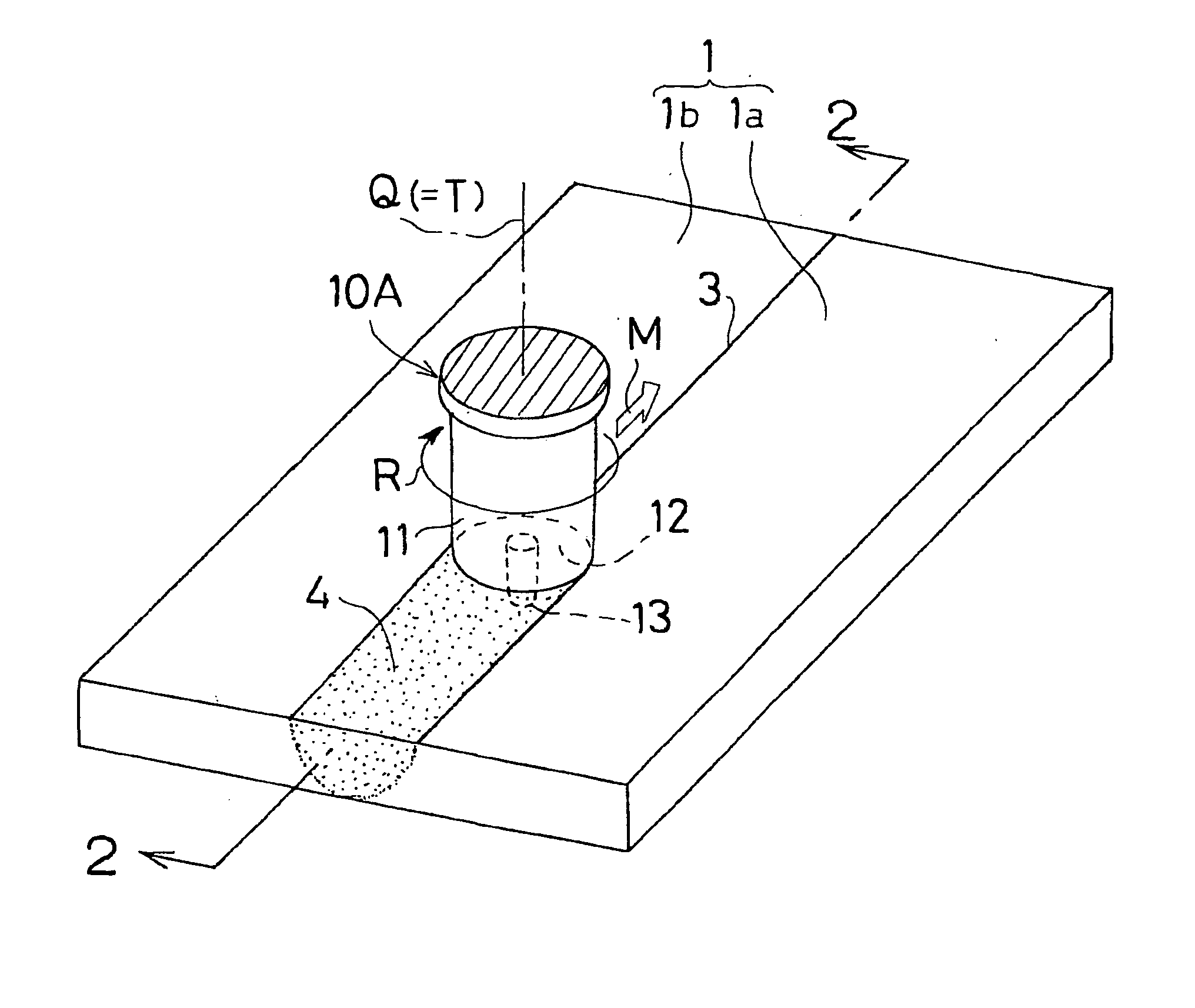
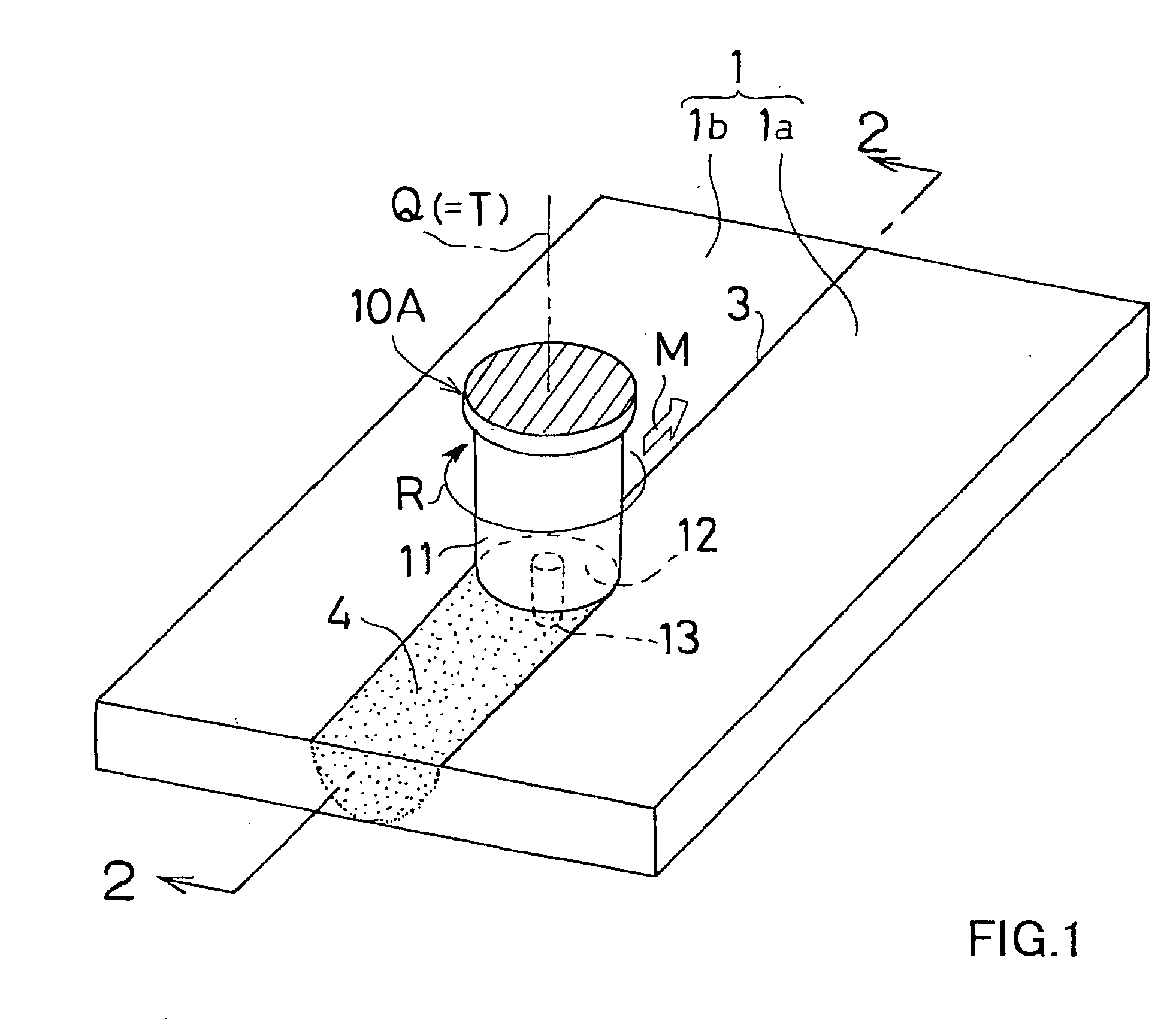
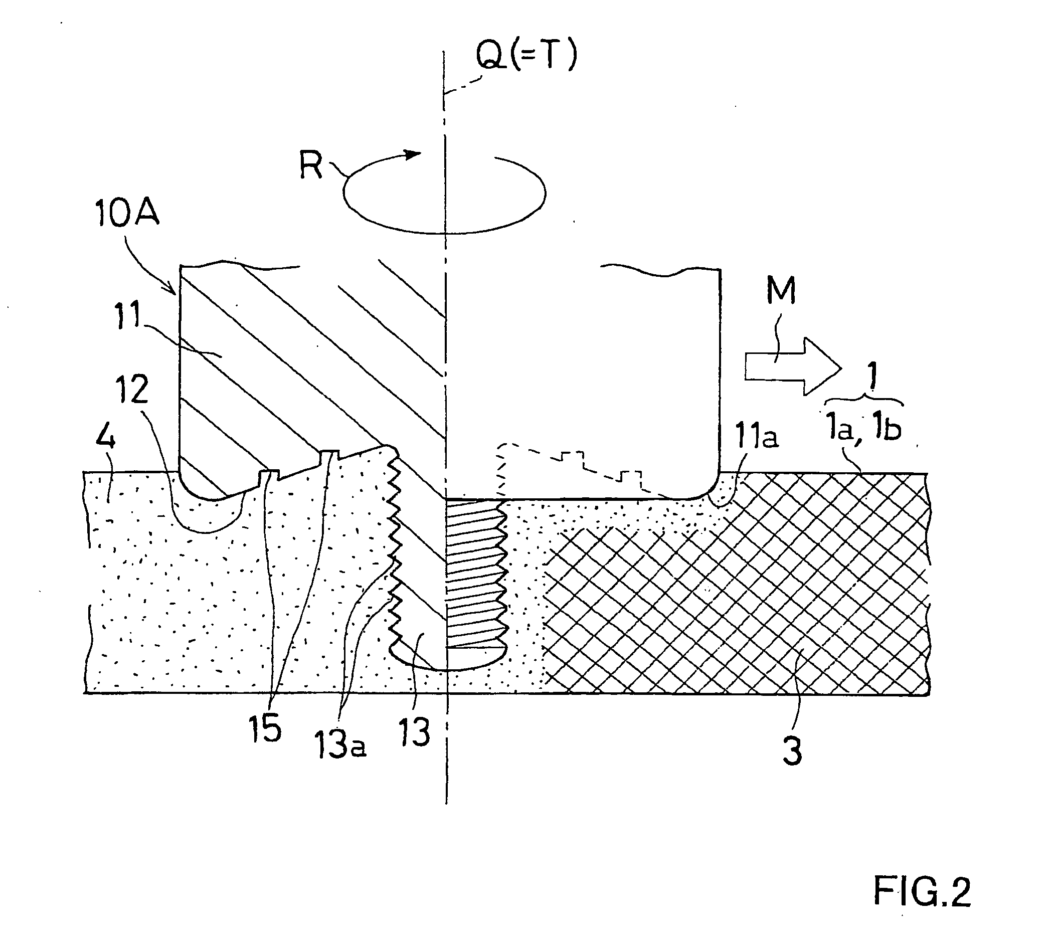
0075] In the first embodiment, the rotational direction R of the rotor 11 is set to the direction as shown in FIG. 3. That is, the rotor 11 is driven in the direction that the groove 15 extends from the center of the end face 12 of the rotor 11 toward the periphery of the end face 12 as seen from the end face 12 of the rotor 11. This enables the materials caught by the groove 15 to be plastically fluidized to gather toward the probe 13 in accordance with the rotation of the end face 12 of the rotor 11. Therefore, the escape of the.materials can be prevented more assuredly to thereby form a better joined portion 4.
0076] In the aforementioned friction agitation joining method, the joining tool 10A in which the end face 12 of the end portion of the rotor 11 is formed into the aforementioned concave surface having the aforementioned spiral groove 15 is used. Therefore, the materials of the joining-members 1a and 1b can be held firmly inside the concave end face 12 without inclining the rotational axis Q of the rotor 11 rearward relative to the joining direction M. Thus, with the joining tool 10A, the advancing operation of the end portion of the rotor 11 (i.e., joining operation) can be done in the state that the rotation axis Q of the rotor 11 coincides with the normal line T of the surfaces of the joining-members 1a and 1b at the prove inserted position (i.e., Q=T), or in the state that the rotation axis Q is positioned in the flat plane perpendicular to the joining direction M. Accordingly, the advancing operation of the end portion of the rotor 11 (i.e., joining operation) can be easily performed even in cases where the butted portion 3 curves (not shown) as well as where the butted portion 3 extends straightly as in the present embodiment.
0077] Furthermore, according to the joining tool 10A, since the materials of the joining-members 1a and 1b can be held firmly in the concave end face 12, joining defects (e.g., hollow portions) due to the lack of materials, and burrs due to the escape of the materials can be prevented. In addition, the thickness of the joined portion can be prevented from being decreased. Accordingly, a joined member with good joining condition can be obtained using the aforementioned joining tool 10A.

Problems solved by technology

Therefore, it was difficult to perform the joining operation.
The joining operation was particularly difficult when the joining portion curved along a circular line or the like.

Method used


Image

  • Friction agitation joining tool, friction agitation joining method and joined member manufacturing method
  • Friction agitation joining tool, friction agitation joining method and joined member manufacturing method
  • Friction agitation joining tool, friction agitation joining method and joined member manufacturing method

Examples


example 2

[0105] The butted portion of the aforementioned joining-members was joined along the entire length thereof using the joining tool 10B according to the second embodiment shown in FIGS. 5 and 6. The dimension of the groove of the joining tool 10B and the joining conditions employed in this example are shown below. The other dimensions of the joining tool and the joining conditions were the same as in the above Example 1.

[0106] [Dimension of the groove of the joining tool]

[0107] Width of the groove w2 . . . 1 mm

[0108] Average depth of the groove h2 . . . 1 mm

[0109] Pitch of the groove p2 . . . 2 mm

example 3

[0110] The butted portion of the aforementioned joining-members was joined along the entire length thereof using the joining tool 10C according to the third embodiment as shown in FIGS. 7 and 8. The dimensions of the groove of the joining tool 10C and the joining conditions employed in this example are shown below. The other dimensions of the joining tool and the joining conditions were the same as in the above Example 1.

[0111] [Dimension of the stepped portion of the joining tool]

[0112] Radius difference between the adjacent stepped portions s . . . 0.5 mm


PUM

PropertyMeasurementUnit
width wlaaaaaaaaaa
width w2aaaaaaaaaa
radiusaaaaaaaaaa

Abstract

A friction agitation joining tool (10A, 10B) includes a rotor (11) having an end portion to be pressed onto at least one of surfaces of joining members (11a, 1b) and a probe (13) to be inserted into a joining portion (3) of the joining-members (1a, 1b), wherein the probe (13) has a diameter smaller than a diameter of the rotor (11). An end face (12) of the end portion of the rotor (11) is formed into a concave surface dented from a periphery of the end face (12) toward a rotational center of the end face (12). The probe (13) is protruded from the rotational center of the end face (12). The end face (12) is provided with a spiral groove (15) or an annular groove (16) surrounding the probe (13). By performing the joining operation with the joining tool (10A, 10B), a joined member with a good joint can be obtained.

Description

[0001] This application is an application filed under 35 U.S.C. .sctn. 111(a) claiming the benefit pursuant to 35 U.S.C. .sctn. 119(e)(1) of the filing data of Provisional Application No. 60 / 301,422 filed Jun. 29, 2001 pursuant to 35 U.S.C. .sctn. 111(b).[0002] The present invention relates to a friction agitation joining tool, a friction agitation joining method and a joined member manufacturing method. More particularly, the present invention relates to a friction agitation joining tool for joining joining-members made of metal such as aluminum or its alloy, a friction agitation joining method and a joined member manufacturing method using the joining tool.[0003] A friction agitation joining method, which is one type of solid-phase joining method, has advantages in that the method can be applied to various joining-members irrespective of the kind metallic materials and causes less thermal stress due to the joining. In recent years, this method has been used as a joining means for ...

Claims


Application Information

Patent Timeline
Patent Type & Authority Applications(United States)
IPC IPC(8): B23K20/12
CPCB23K2203/10B23K20/1255B23K2103/10B23K20/12
Inventor HASHIMOTO, TAKENORIJHOGAN, SHIGETOSHINAGANO, YOSHITAKA
Owner SHOWA DENKO KK
Why Eureka
Try Eureka