
Mini-coax cable connector and method of installation

Inactive Publication Date: 2004-06-10
PPC BROADBAND INC +1
View PDF0 Cites 29 Cited by
  • Summary
  • Abstract
  • Description
  • Claims
  • Application Information

AI Technical Summary

Benefits of technology

[0005] It is another object of the present invention to provide for a novel and improved adapter for small diameter coaxial cables which can be installed in the field in a minimum number of steps with minimal tooling required.
[0006] It is a further object of the present invention to provide for a novel and improved adapter for coaxial cable installations which assures accurate alignment between the cable and connector preliminary to crimping of the connector onto the cable and prevents shorting between the cable layers with one another as well as with conductive portions of the connector.
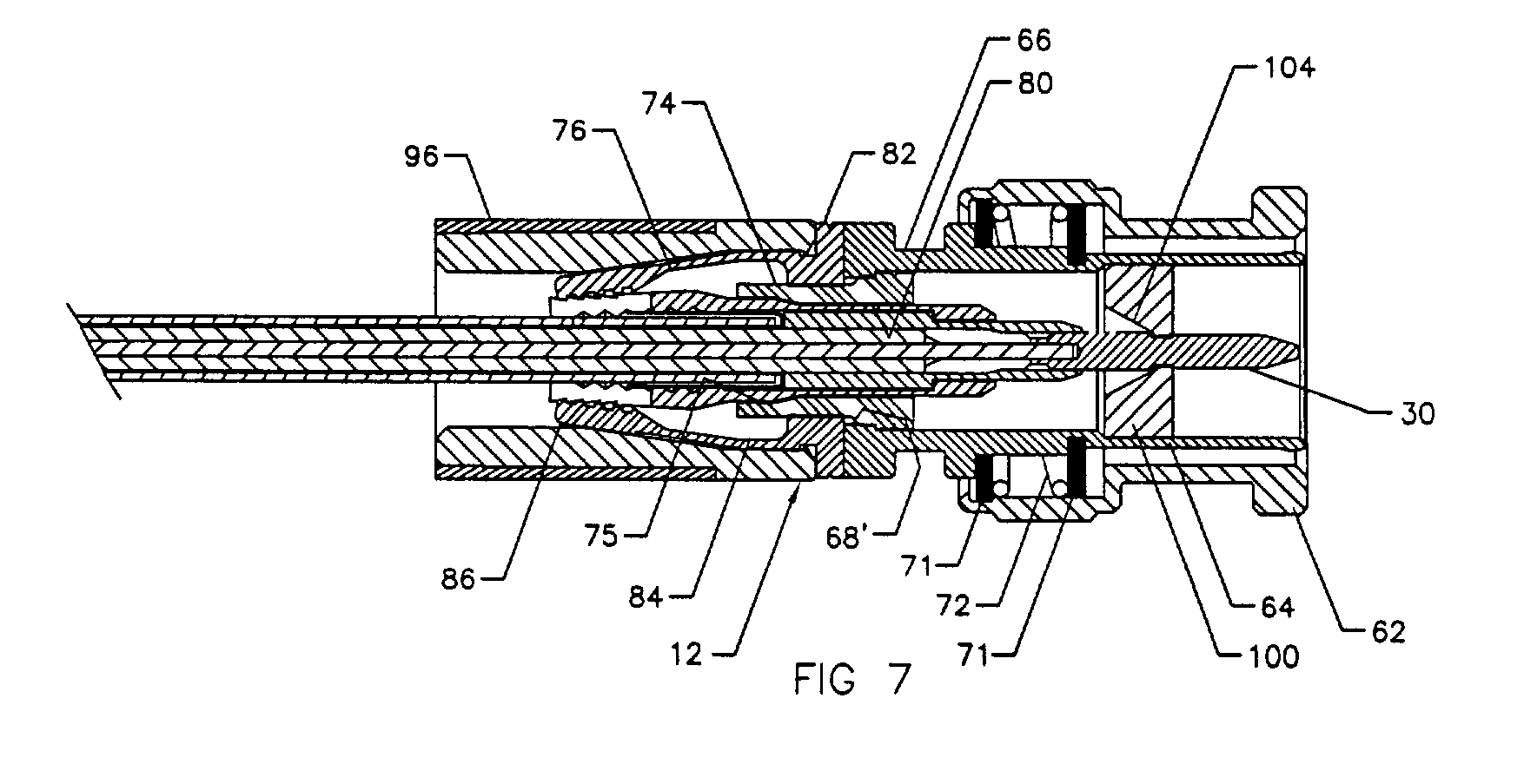
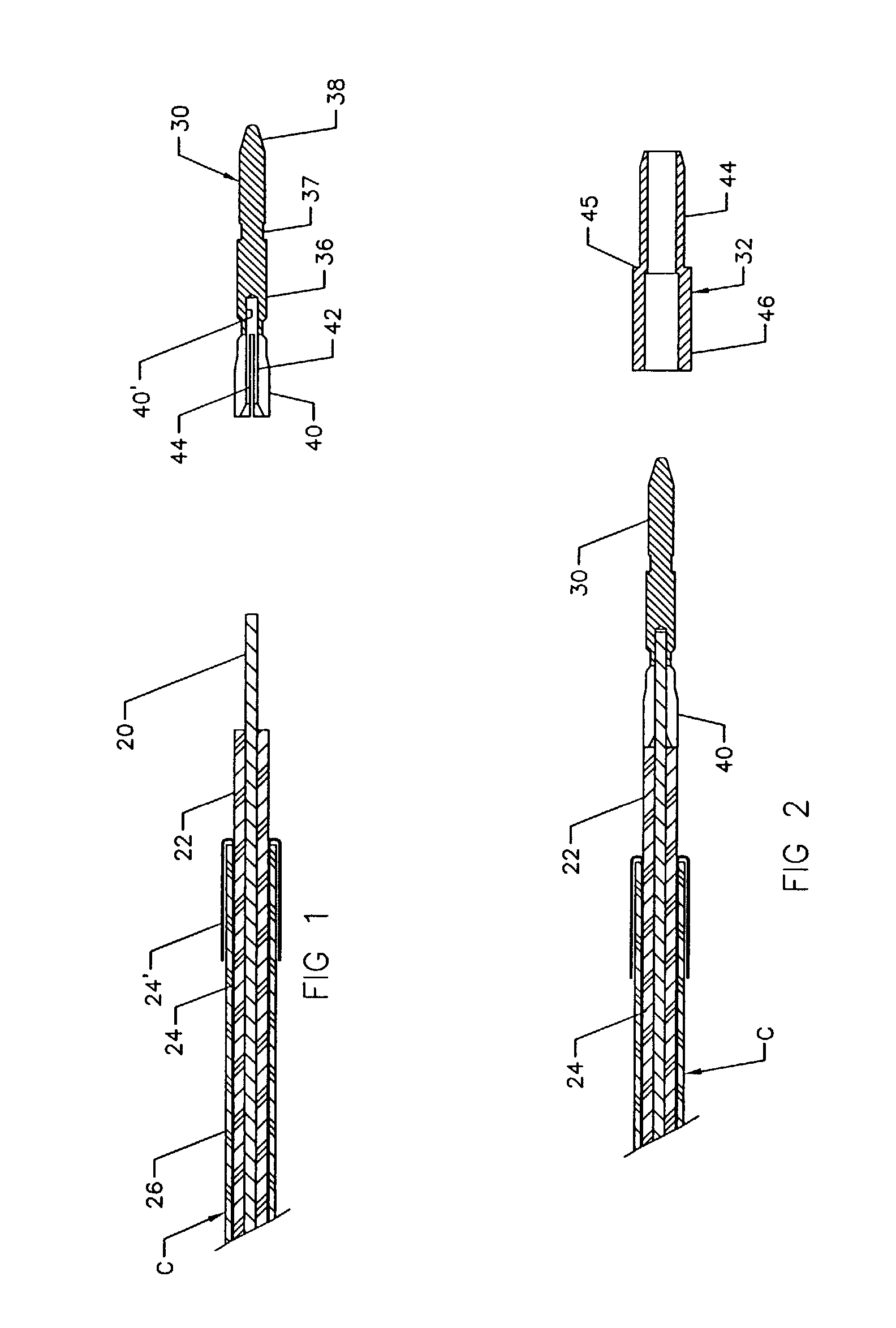
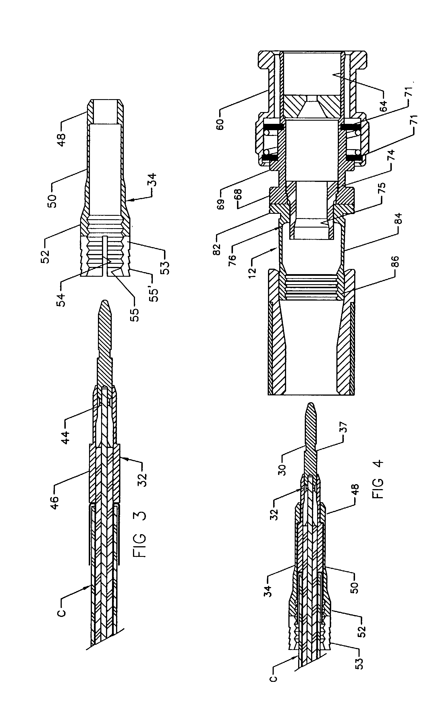
[0008] In accordance with the present invention, an adapter is provided for connecting the end of a coaxial cable to a hollow connector body wherein the cable is of the type having inner and outer concentric electrical conductors, an annular dielectric separating the conductors and an outer jacket of electrically non-conductive material, the inner and outer conductors being exposed and the inner conductor projecting beyond the dielectric at one end of the cable; and the adapter comprises an extension tip of electrically conductive material provided with a recess into which the inner conductor can be inserted, a first sleeve of electrically non-conductive material surrounding the dielectric layer, and a second sleeve of electrically conductive material surrounding the exposed end of the outer conductor. In a preferred form thereof, the first sleeve is dimensioned such that it can be advanced over the extension tip and will cause a trailing end of the extension tip to be compressed snugly into firm engagement with the central conductor pin. Further, the second sleeve is dimensioned to advance over both the tip and plastic sleeve, and a reduced or thicker portion of the second sleeve will bear against an enlarged portion of the first sleeve and at the same time stiffen or rigidify the entire adapter assembly. The sleeves are dimensioned such that a standard size crimping ring, for example, on a BNC connector will cause the second sleeve to be compressed into sealed engagement with the end of the cable, and the first sleeve will insulate the outer conductive braided layer from shorting. In addition, a trailing end of the second sleeve is slotted to divide the trailing end into prong-like segments having internal and external teeth so that when the trailing end of the second sleeve can be compressed into engagement with the cable without crushing the dielectric layer.

Problems solved by technology

A difficulty in using the smaller cables however is in manually preparing the cable to connect to a post or terminal in the field.
For example, there is the problem of separating the conductive and non-conductive layers when preparing the end of the cable for connection and in such a way as to prevent shorting between layers.
It is extremely difficult to force a sleeve on the BNC connector between the dielectric and braided layers and often leads to shorting between the conductive braid layer and center conductor wire or pin.

Method used


Image

  • Mini-coax cable connector and method of installation
  • Mini-coax cable connector and method of installation
  • Mini-coax cable connector and method of installation

Examples


Embodiment Construction

[0018] Referring in more detail to the drawings, the present invention may be best typified by describing a novel form of termination assembly in combination with a standard RGB mini-coax cable C and a BNC connector 12 modified in a manner to be described.

[0019] As a setting for the present invention, the cable C is made up of an inner or central conductor pin or wire 20 which is surrounded by a dielectric insulator 22 of electrically non-conductive material, such as, a rubber or rubber-like material, a braided conductor layer 24, and an outer jacket 26 of an electrically non-conductive material, such as, a rubber or rubber-like material. The end of the cable C is further prepared for assembly by removing a limited length of the outer jacket 26 and braided conductor 24, and another limited length of the insulator layer 22 is removed to expose an end of the pin 20 along with the foil layer 21 surrounding the pin 20. The braided conductor layer 24 is peeled back and away from the insu...


PUM


Abstract

An adaptor or termination assembly for a mini-coax cable is made up of an extension tip which receives the inner conductor pin on the cable, a first sleeve which fits over an exposed end of the dielectric layer, and a second sleeve which surrounds an exposed end of the outer conductor, all as a preliminary to inserting the assembly into a standard sized connector body and assuring a positive connection between the cable and connector body in such a way as to avoid creating impedance which will downgrade the signal passing through the cable into the connector.

Description

BACKGROUND AND FIELD OF INVENTION[0001] This invention relates to coaxial cable connecting devices; and more particularly relates to a novel and improved adapter for connecting mini-coax cables to a connector.[0002] Mini-coax cables are increasingly being used in installations having space limitations and where only a short run of cable is needed. Typically, the mini-coax cables are on the order of 2.5 mm. to 4 mm. in diameter. Typical applications for such cables are for security cameras as well as telecommunications. A difficulty in using the smaller cables however is in manually preparing the cable to connect to a post or terminal in the field. For example, there is the problem of separating the conductive and non-conductive layers when preparing the end of the cable for connection and in such a way as to prevent shorting between layers. A typical example is in connecting to a BNC connector having a preassembled crimping ring, such as, that set forth and described in my U.S. Pat....

Claims


Application Information

Patent Timeline
IPC IPC(8): H01R9/05H01R13/646
CPCH01R2103/00H01R9/0524
Inventor HOLLIDAY, RANDALL A.WONG, SHENG CHIA
Owner PPC BROADBAND INC
Learn More