Delivery system for a stentless valve bioprosthesis

a bioprosthesis and delivery system technology, applied in the field of tubular prosthesis, can solve the problems of limiting interactions with aortic wall dynamics, increasing heart work burden, inhibiting natural valve movement, etc., and achieve the effect of improving recovery and reducing patient's hospital stay

Inactive Publication Date: 2004-06-10
3F THERAPEUTICS
View PDF3 Cites 416 Cited by
  • Summary
  • Abstract
  • Description
  • Claims
  • Application Information

AI Technical Summary

Benefits of technology

[0007] Porter in U.S. Pat. No. 5,064,435 discloses a catheter-based apparatus and methods for releasing a self-expandable prosthesis by a conventional pushing mechanism. The above-mentioned approaches are satisfactory for delivering a stented prosthesis having an external rigid support adapted for receiving the pushing force. A self expanding prosthesis often is preferred over a plastically deformed device. Resilient prosthesis can be deployed without dilatation balloons or other stent expanding means. A self-expanding prosthesis can be preselected in accordance with the diameter of the body channel or other anatomic site for fixation. While deployment requires skill in positioning the prosthesis, the added skill of properly dilating the balloon to plastically expand a prosthesis to a selected diameter is not required. Also, the self-expanding prosthesis remains at least slightly compressed after fixation, and thus has a restoring force which facilitates acute fixation.
[0009] The main disadvantage to stentless valves has been in their difficulty of deployment and implantation, particularly in a catheter-based percutaneous route. With recent scientific advancements in robotics, instrumentation and computer technology, a minimally invasive catheter-based delivery system for a stentless bioprosthesis is imminent. There is currently a clinical need for deploying a tubular stentless prosthesis, such as a stentless valve or a vascular graft without a rigid support, into a body channel, preferably by a percutaneous approach. The catheter-based percutaneous delivery system as compared to an open-cavity surgery will greatly reduce the patient's hospital stay and improve recovery.

Problems solved by technology

Inevitably, however, a stent limits interactions with aortic wall dynamics and tends to inhibit natural valve movement.
This results in post-operative transvalvular gradients with resultant additional work burden on the heart.

Method used


Image

  • Delivery system for a stentless valve bioprosthesis
  • Delivery system for a stentless valve bioprosthesis
  • Delivery system for a stentless valve bioprosthesis

Examples


Embodiment Construction

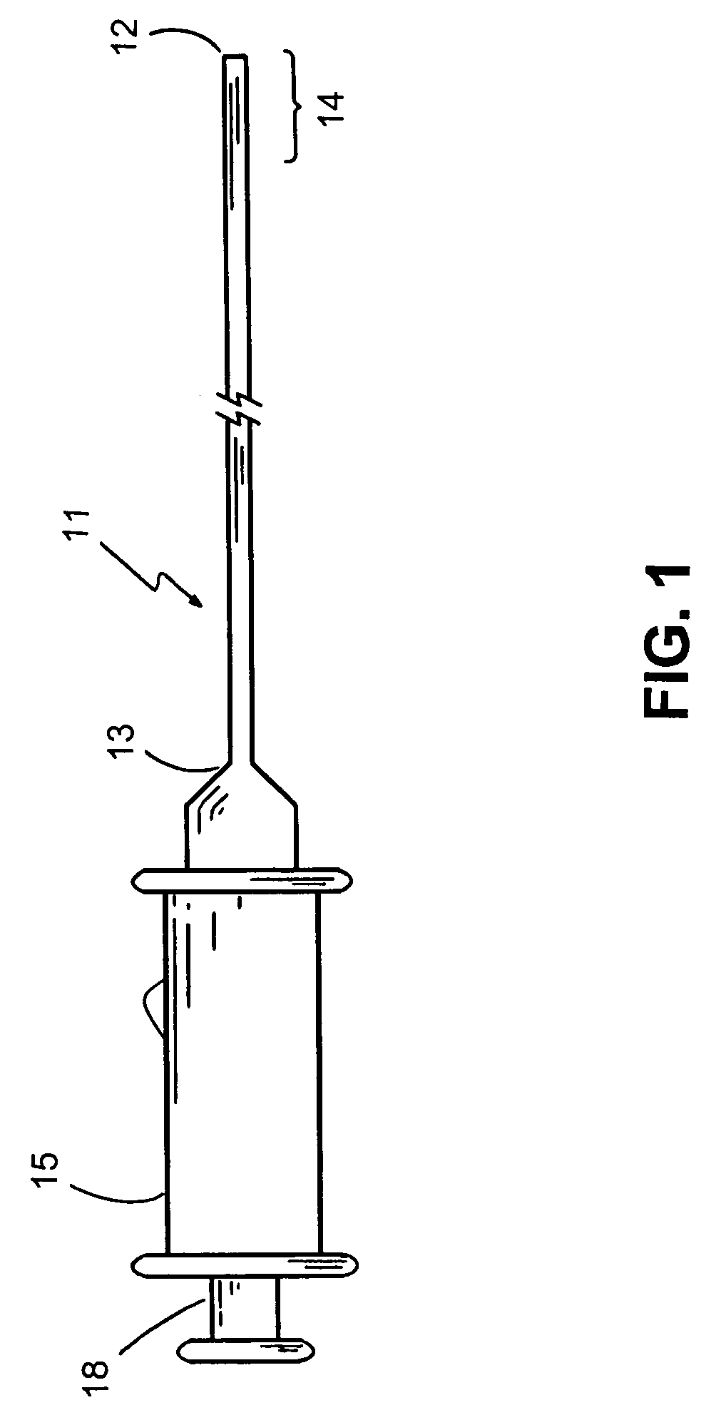
[0023] Referring to FIGS. 1 to 5, what is shown is an embodiment of the device delivery system and methods, comprising a delivery catheter adapted particularly for delivering a tubular stentless prosthesis to an anatomical site in a body channel.

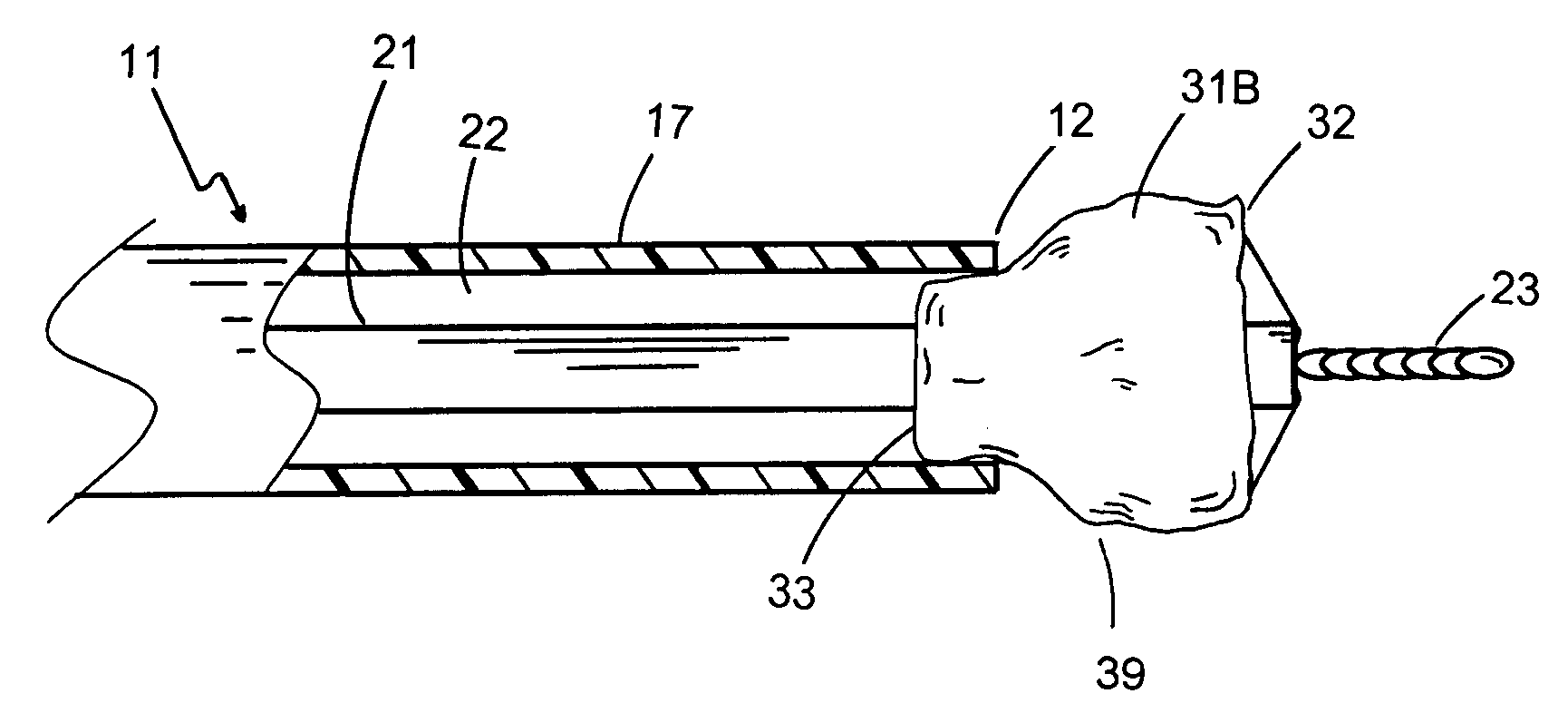
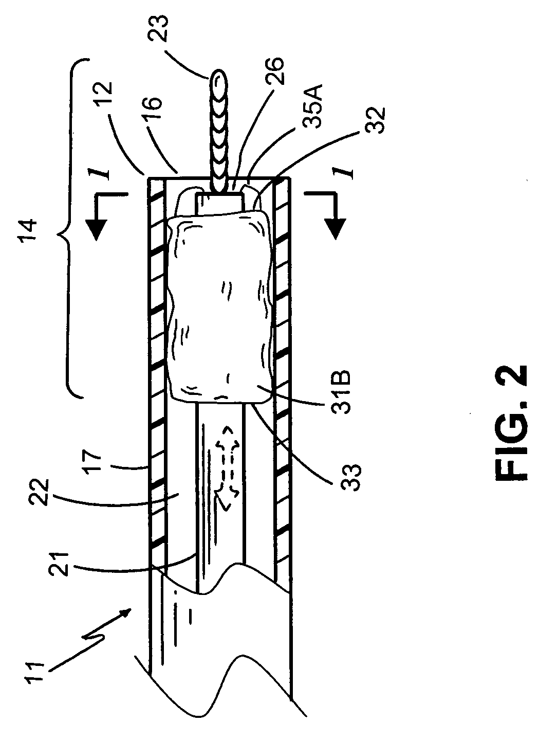
[0024] FIG. 1 shows an overall view of a delivery catheter of the present invention for delivering a tubular stentless prosthesis into a body channel. A tubular stentless prosthesis is a prosthesis without a support or stent. Typically such a prosthesis is soft, flexible and very compressible or collapsible either radially or longitudinally. The best handling method is to hold it in its natural position without buckling, compression, or "spaghetti-like" twisting. When such a prosthesis 31 is held horizontally, the best way to move it in an essentially straight manner is to pull the distal section 32 forward rather than push its proximal end 33.

[0025] The catheter 11 of the present invention comprises a catheter shaft 17, the catheter shaft h...


PUM


Abstract

The current invention discloses a catheter and a method for delivering a stentless bloprosthesis in a body channel, the method comprising percutaneously introducing a catheter into the body channel, wherein the catheter contains said stentless bloprosthesis at a retracted state; and disengaging said stentless bioprosthesis out of a distal opening of the catheter by a pulling mechanism associated with the catheter structure.

Description

[0001] This application claims priority to U.S. Utility application Ser. No. 09 / 853,463, filed May 10, 2001, the entirety of which is hereby incorporated by reference.TECHNICAL INVENTION[0002] The present invention generally relates to a tubular prosthesis and methods for delivery into a body channel. More particularly, the present invention relates to an improved delivery system for delivering a stentless bioprosthesis comprising a collapsible elastic valve or a biological graft at a desired anatomical site of the body channel for implantation.[0003] A prosthetic heart valve may be used to replace a diseased natural heart valve in a human patient. Similarly, a prosthetic venous valve may be used to replace a dysfunctional natural venous valve in a patient. Mechanical heart valves typically have a rigid orifice ring and rigid hinged leaflets coated with a blood compatible substance such as pyrolytic carbon. Other configurations, such as ball-and-cage assemblies, have also been used ...

Claims


Application Information

Patent Timeline
Patent Type & Authority Applications(United States)
IPC IPC(8): A61F2/24
CPCA61F2/2412A61F2/2475A61F2/2436
Inventor TU, HOSHENGQUIJANO, RODOLFO C.
Owner 3F THERAPEUTICS
Why Eureka
Try Eureka