Method and apparatus for directional resistivity measurement while drilling

a directional resistivity and drilling method technology, applied in the field of electric resistivity well logging methods, can solve the problems of lack of azimuthal resolution, inability to distinguish whether a layer is above or below the borehole, and coaxial coil transmitters and receivers

Active Publication Date: 2004-06-17
BAKER HUGHES HLDG LLC
View PDF7 Cites 57 Cited by
  • Summary
  • Abstract
  • Description
  • Claims
  • Application Information

AI Technical Summary

Problems solved by technology

Therefore, in a horizontal wellbore, the data do not contain information about directionality of the formation therefore, It is not possible to distinguish whether a layer is above or below the borehole from these data alone.
These tools, however, employ coaxial-coil transmitters and receivers and are lack of azimuthal resolution.

Method used


Image

  • Method and apparatus for directional resistivity measurement while drilling
  • Method and apparatus for directional resistivity measurement while drilling
  • Method and apparatus for directional resistivity measurement while drilling

Examples


Embodiment Construction

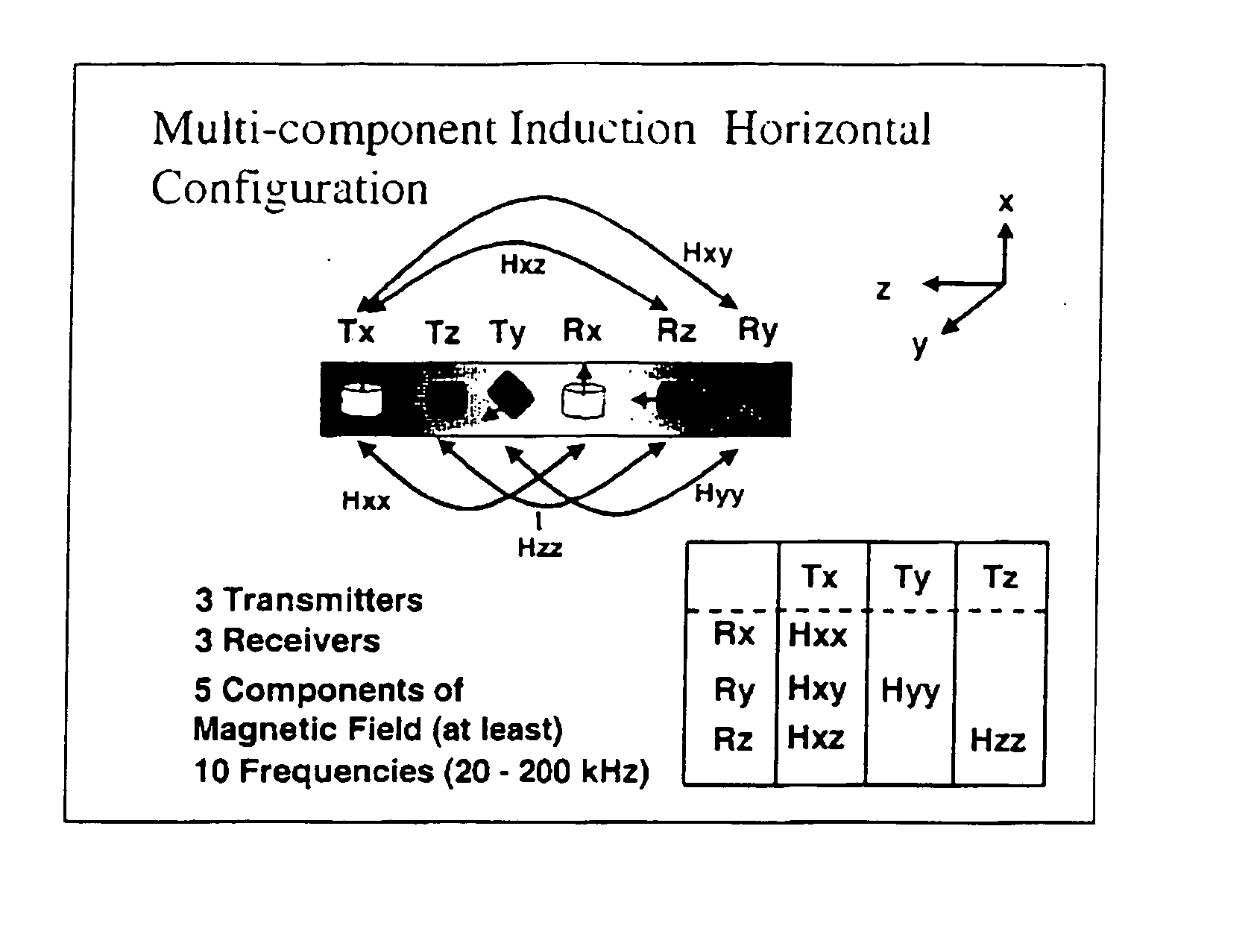
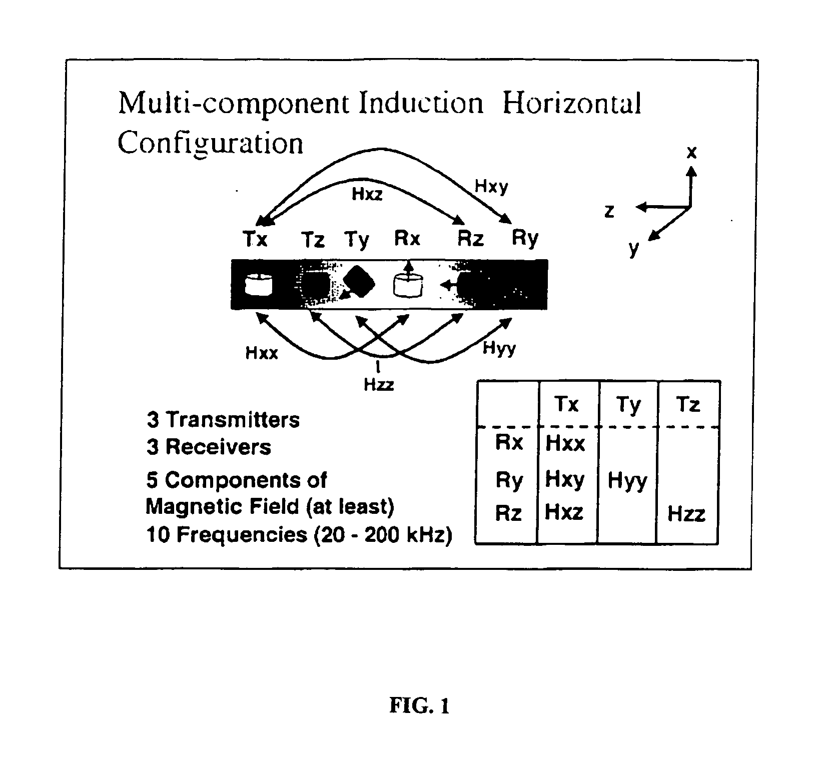
[0023] FIG. 1 shows the configuration of transmitter and receiver coils in a preferred embodiment of the 3DExplorer.TM. (3DEX) induction logging instrument of Baker Hughes. Three orthogonal transmitters 101, 103, and 105 that are referred to as the T.sub.x, T.sub.z, and T.sub.y transmitters are placed in the order shown. The three transmitters induce magnetic fields in three spatial directions. The subscripts (x, y, z) indicate an orthogonal system substantially defined by the directions of the normals to the transmitters. The z-axis is chosen to be along the longitudinal axis of the tool, while the x-axis and y-axis are mutually perpendicular directions lying in the plane transverse to the axis. Corresponding to each transmitter 101, 103, and 105 are associated receivers 111, 113, and 115, referred to as the R.sub.x, R.sub.z, and R.sub.y receivers, aligned along the orthogonal system defined by the transmitter normals, placed in the order shown in FIG. 1. R.sub.x, R.sub.z, and R.su...


PUM


Abstract

A measurement-while-drilling or logging while drilling method and apparatus for determining the azimuth of providing magnetic field in a remote formation layer in the vicinity of a down hole resistivity tool. A cross-component magnetic field with substantially orthogonal transmitter and receiver coils is provided. The coil planes are either substantially orthogonal (coaxial coils) or parallel (transverse coils) with respect to, the longitudinal axis of the tool body. The coils are placed on the tool body having a external surface and a plurality of grooves are cut in the external surface of the tool body and oriented substantially horizontally with respect to the longitudinal axis of the tool body for the coils and oriented vertically with respect to the longitudinal axis of the tool body for the coaxial coils. A transverse and coaxial coil are placed in the grooves for transmission or reception of a cross-component transverse magnetic field. Ferrite materials may be inserted in the grooves in between the coil wire and the bottom of the grooves. Multiple receivers, transmitters and frequencies may be used to obtain the maximum possible signal-to-noise ratio. The in-phase or quadrature part of a magnetic field, or a combination of the two, or alternatively, the amplitude and / or phase, of the cross-component magnetic field may be measured and processed to indicate the azimuth of a remote layer boundary, provided that the layer boundary is within the depth of investigation of the tool. Measurements may also be made at continuous or multiple tool azimuths.

Description

[0001] This patent application claims priority from U.S. Provisional Patent Application serial No. 60 / 408,615 filed on Sep. 6, 2002 entitled Method and Apparatus for the Use of Multicomponent Induction Tool and Cross Component Measurements for Geosteering and Formation Resistivity Data Interpretation in Horizontal Wells" by Tsili Wang, et al. which is incorporated herein by reference in its entirety.[0002] 1. Field of the Invention[0003] The invention is related generally to the field of electrical resistivity well logging methods. More specifically, the invention is related to a method and apparatus for providing a transverse coil and measuring cross-component magnetic fields in a downhole resisitivity tool.[0004] 2. Description of the Related Art[0005] Electromagnetic induction and wave propagation logging tools are commonly used for determination of electrical properties of formations surrounding a borehole. These logging tools give measurements of apparent resistivity (or conduc...

Claims


Application Information

Patent Timeline
Patent Type & Authority Applications(United States)
IPC IPC(8): G01V3/28
CPCG01V3/28
Inventor WANG, TSILITABAROVSKY, LEONTYTCHAKAROV, BORISSIGNORELLI, JOHNFANG, SHENG
Owner BAKER HUGHES HLDG LLC
Why Eureka
Try Eureka