Camera apparatus, a camera system, and a method for controlling the camera system

a camera system and camera technology, applied in the field of camera systems and camera systems, can solve the problems of inability to focus on the subject, difficult to track a subject at an optimal speed, and composite cameras according to the related art cannot address this problem

Inactive Publication Date: 2004-06-17
PANASONIC CORP
View PDF4 Cites 9 Cited by
  • Summary
  • Abstract
  • Description
  • Claims
  • Application Information

AI Technical Summary

Problems solved by technology

However, on the former composite camera which performs speed control depending on the zooming magnification information held in the camera alone, it is difficult to track a subject at an optimum speed in case the height of the camera location or distance to the subject has changed.
On the other hand, on the latter composite camera which adjusts and controls the swivel speed in accordance with the angle of the camera direction, there remains the problem: in case the angle of the camera direction is the sole information available, it is possible to capture a subject within the sight but could be impossible to focus on the subject when the distance to the camera changed while the subject was moving.
The composite camera according to the related art cannot possibly address this problem.

Method used


Image

  • Camera apparatus, a camera system, and a method for controlling the camera system
  • Camera apparatus, a camera system, and a method for controlling the camera system
  • Camera apparatus, a camera system, and a method for controlling the camera system

Examples


first embodiment

[0070] (First Embodiment)

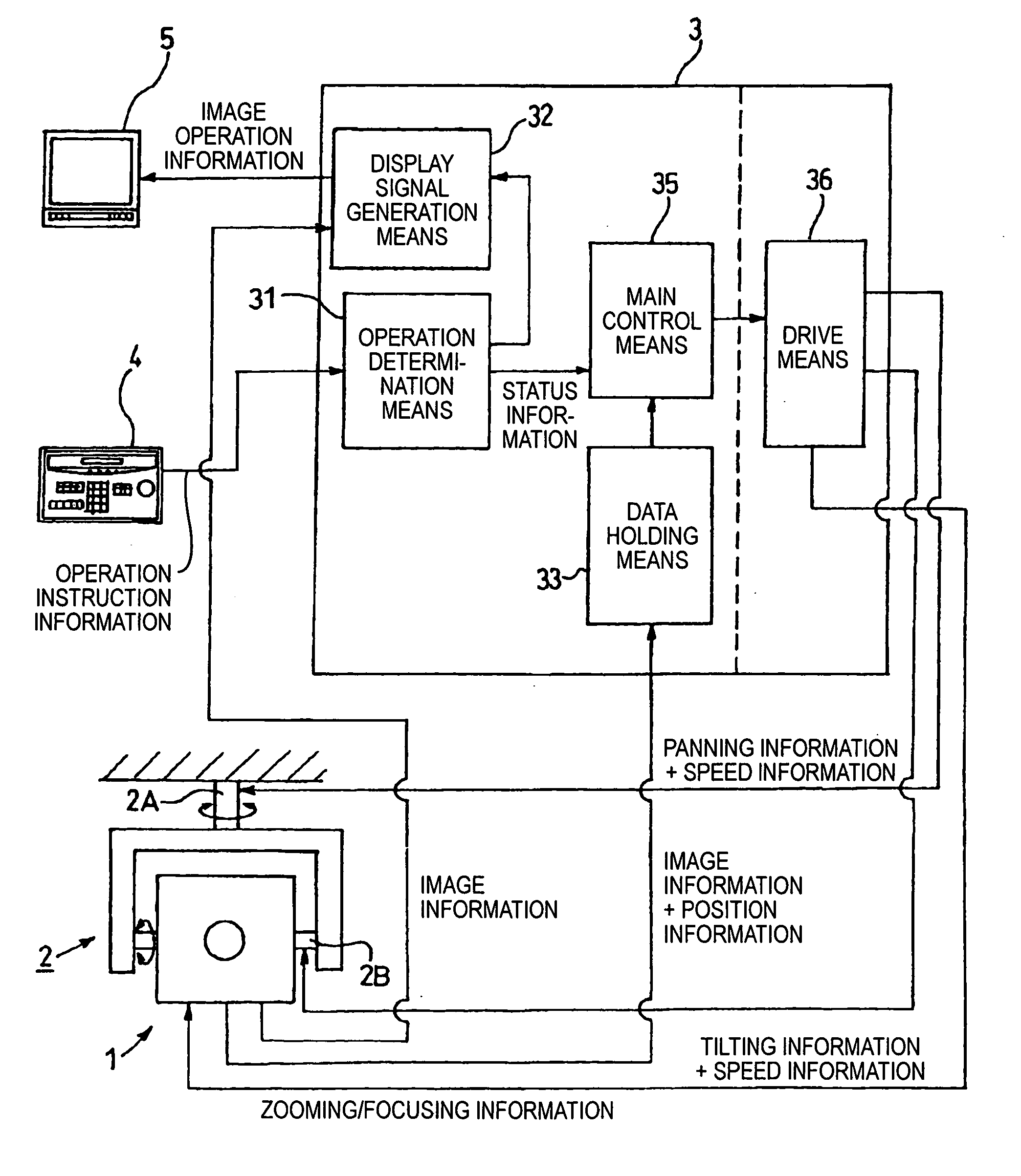
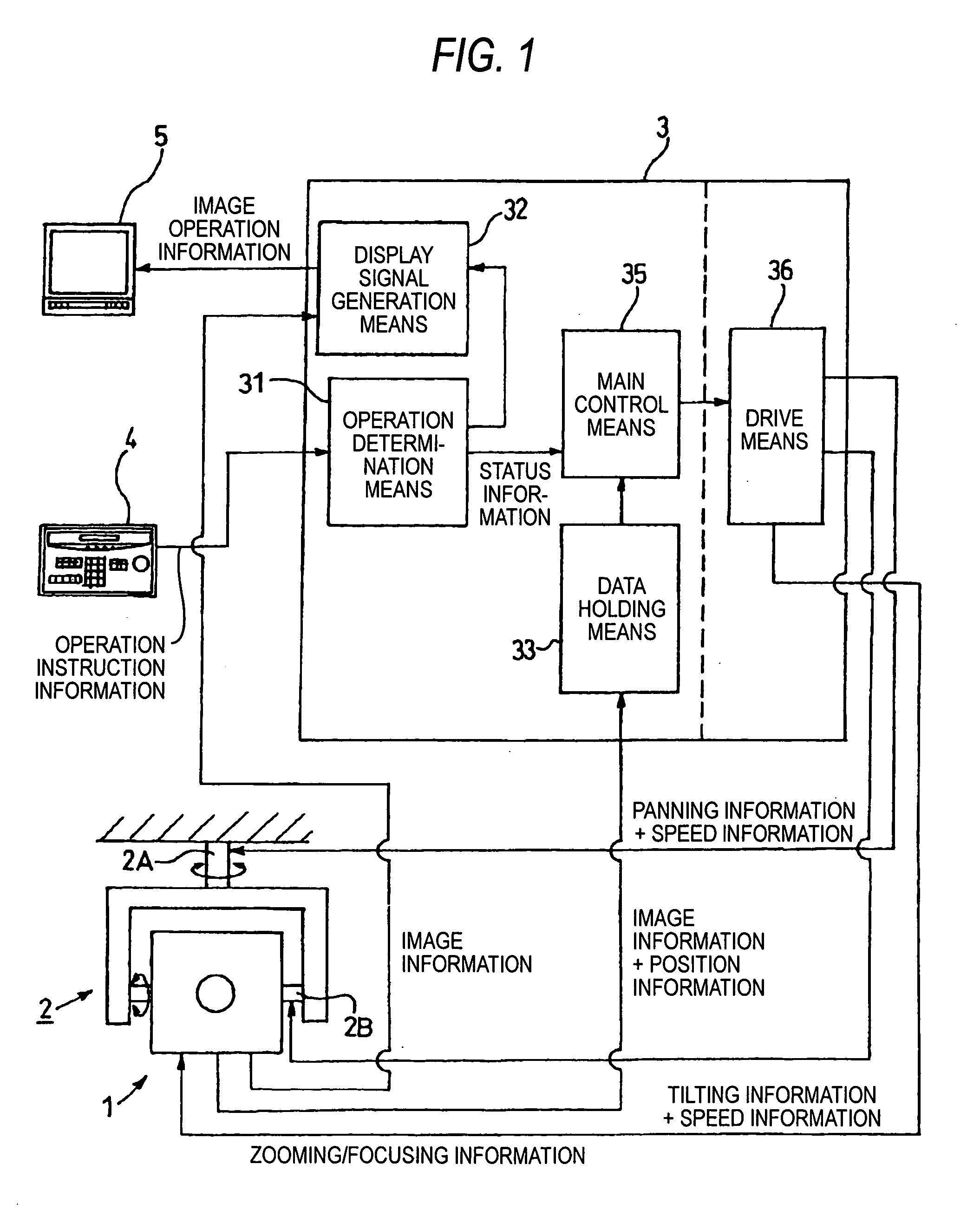
[0071] FIG. 1 is a block diagram showing a camera system comprising surveillance camera apparatus equipped with a function to control the speed of a rotating body according to the first embodiment of the invention. The camera system drives the rotting body 2 based on the operation instruction information received from an input operation unit 4 mentioned later and the information on the distance to a subject held in a controller 3. The camera system generally comprises: surveillance camera apparatus including a camera main body 1, the rotating body 2 where the camera main body 1 is rotatably attached and the controller 3; the input operation unit 4; and a monitor unit 5.

[0072] The camera main body 1 is capable of performing panning and tilting operations (subject tracking operation) by way of the rotating body 2. Thus the rotating body 2 comprises a panning mechanism and a tilting mechanism as rotation means. Theses mechanisms are driven and controlled by the...

second embodiment

[0092] (Second Embodiment)

[0093] The second embodiment of the invention will be detailed referring to FIG. 3. In this embodiment, the same components as those in the first embodiment are given the same numerals and signs to avoid duplicate explanation.

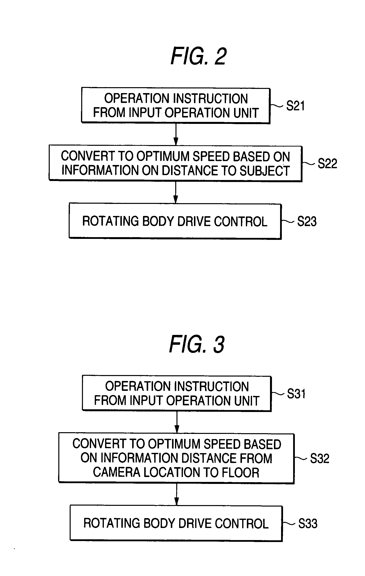
[0094] The surveillance camera apparatus equipped with a function to control the speed of a rotating body according to the second embodiment of the invention performs arithmetic operation of an optimum speed and converts the current operation speed to the optimum speed based on the operation speed instruction information as operation instruction information input from the input operation unit 4 and the information on the distance from the camera location to the floor as status information held in the controller 3, and drives / controls the rotating body 2 at the optimum speed.

[0095] FIG. 3 is a flowchart showing the operation of the surveillance camera apparatus equipped with a function to control the speed of a rotating body according t...

third embodiment

[0105] (Third Embodiment)

[0106] The third embodiment of the invention will be detailed referring to FIG. 3. In this embodiment, the same components as those in the first embodiment are given the same numerals and signs to avoid duplicate explanation.

[0107] The surveillance camera apparatus equipped with a function to control the speed of a rotating body according to the second embodiment of the invention performs arithmetic operation of an optimum speed and converts the current operation speed to the optimum speed based on the operation speed instruction information input from the input operation unit 4 and the information on the orientation of the camera in vertical direction held in the camera main body 1, and drives / controls the rotating body 2 at the optimum speed.

[0108] FIG. 4 is a flowchart showing the operation of the surveillance camera apparatus equipped with a function to control the speed of a rotating body according to the third embodiment of the invention. The flowchart...


PUM


Abstract

Providing camera apparatus and a camera system capable of performing optimum speed control by themselves and even facilitate tracking of a subject by way of a plurality of cameras while using a same controller, even in case the location of the camera or the distance between the camera and the subject has changed, and a method for controlling the camera system The camera apparatus includes: a camera for photographing a subject; a rotating body for rotating the camera in order to track the subject; and a controller for controlling the motion of the rotating body and the operation of the camera; characterized in that the controller includes: an operation determination unit for analyzing and determining the input operation instruction information on the rotating body and the camera; a data holding unit for holding the status information on the photographing operation of the camera; a main control unit for calculating an optimum speed to track the subject based on the information output from the operation determination unit and the data holding unit and outputting the speed to the rotating body; and a drive unit for driving the rotating body.

Description

[0001] 1. Field of the Invention[0002] The present invention relates to a camera, zooming means, focusing means, motion detection means and a power source provided in combination, and in particular to camera apparatus and a camera system which are capable of performing speed control of a rotating body facilitating tracking of a subject and are preferably used for surveillance, crime prevention and monitoring, and a method for controlling the camera system.[0003] 2. Description of the Related Art[0004] A surveillance camera, a security camera or a monitor camera equipped with a zooming function and a focusing mechanism (hereinafter referred to as a composite camera) is known. A composite camera is also known comprising a rotating body (panhead) equipped with a rotating mechanism which can rotate the camera main body in order to keep photographing a subject by changing the photographing direction following the motion of the subject.[0005] In the related art, there is known a composite...

Claims


Application Information

Patent Timeline
Patent Type & Authority Applications(United States)
IPC IPC(8): G03B13/36G01S3/786G02B7/08G02B7/28G03B5/00G03B5/06G03B15/00G03B17/12G03B17/56H04N5/225H04N5/232H04N7/18
CPCG01S3/7864H04N7/183G08B13/1963G08B13/19608
Inventor KAWAZOE, SHUUJIKOGANE, HARUO
Owner PANASONIC CORP
Why Eureka
Try Eureka