Transmission control system of automatic transmission for vehicle

a technology of automatic transmission and transmission control system, which is applied in the direction of electric control, machines/engines, instruments, etc., can solve the problems of large transmission shock, rapid engine speed increase, and control according to the u.s. patent no. 5,445,579

Inactive Publication Date: 2004-06-17
JATCO LTD
View PDF5 Cites 7 Cited by
  • Summary
  • Abstract
  • Description
  • Claims
  • Application Information

AI Technical Summary

Benefits of technology

[0013] To prevent a rapid engine speed increase when the accelerator is stepped on before and after an actual transmission start time, to thereby assuredly restrict a transmission shock.
[0022] prevents a changeover to the low speed side change gear, thus keeping the high speed side change gear.

Problems solved by technology

In this case, however, a possible response delay in increasing the actual oil pressure relative to a duty ratio change of a solenoid may cause a rapid engine speed increase.
This may make a determination that the oil pressure is short, thus a controller may increase the oil pressure more than necessary, resulting in a great transmission shock with both the disengagement side clutch engaged and the engagement side clutch engaged.
In other words, the control according to the U.S. Pat. No. 5,445,579 (equivalent of Japanese Patent No. 3097339B2) is not effective for the accelerator stepped on before the actual transmission start time.
More specifically about this: Stepping on the accelerator before the actual transmission start time (a period from a time for commanding a transmission start to a time for starting torque conveyance by the engagement side clutch, during which period torque capacity of the disengagement side clutch is continuously decreased) may cause a slip to the disengagement side clutch, thus causing the rapid engine speed increase.
Thereafter, the oil pressure may follow, thus rapidly engaging the engagement side clutch, resulting in the transmission shock.
In this case, the rapid engine speed increase cannot be prevented assuredly.
The driver therefore cannot obtain a preferred acceleration feeling.

Method used


Image

  • Transmission control system of automatic transmission for vehicle
  • Transmission control system of automatic transmission for vehicle
  • Transmission control system of automatic transmission for vehicle

Examples


first embodiment

[0043] 1. First Embodiment

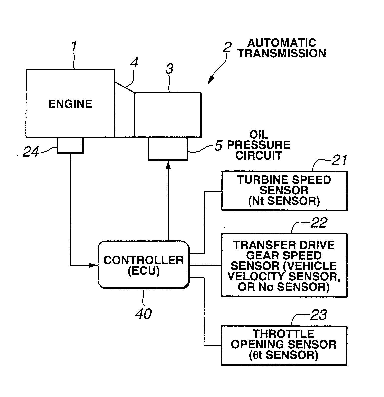
[0044] There is provided a transmission control system of an automatic transmission 2 for a vehicle, according to a first embodiment of the present invention.

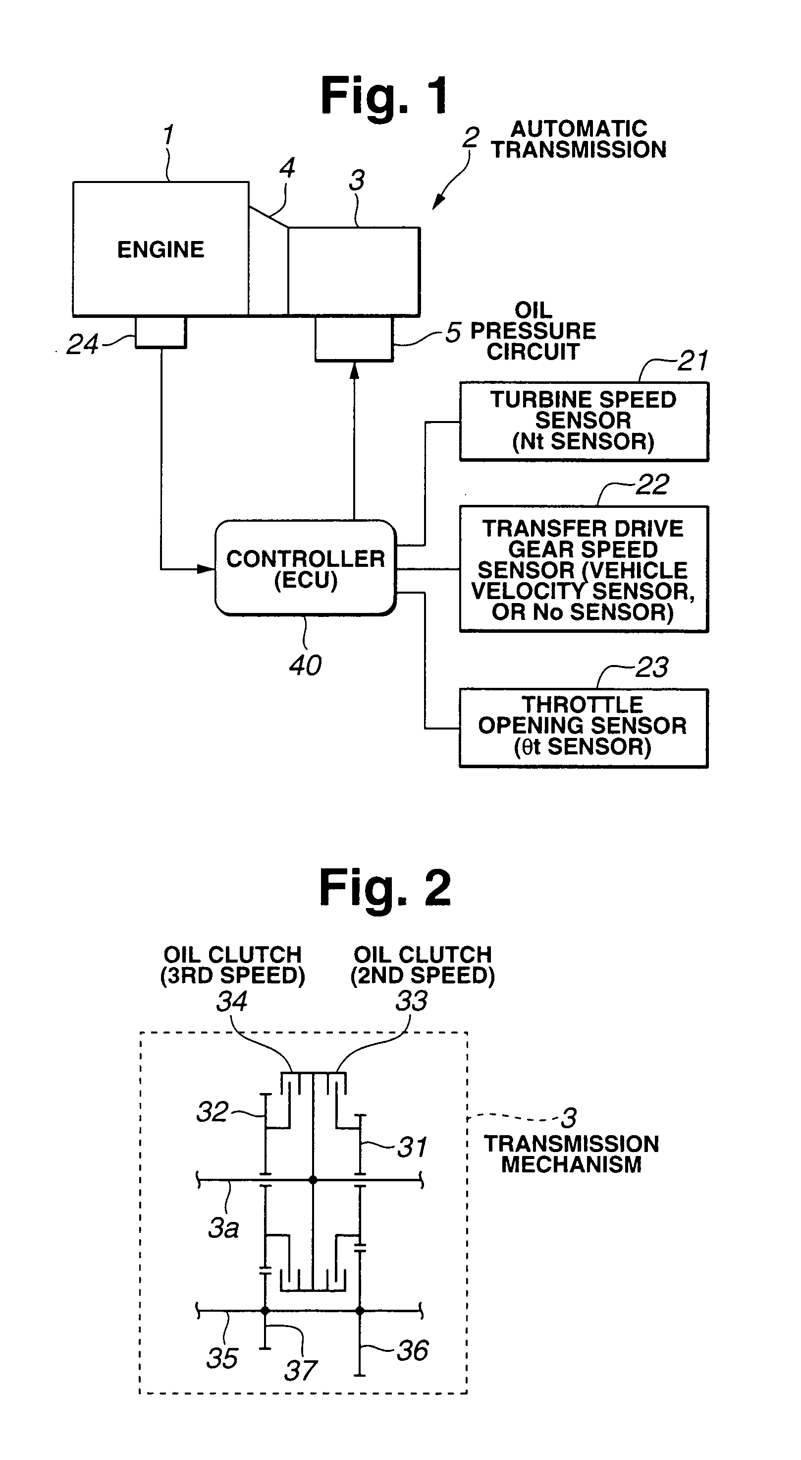
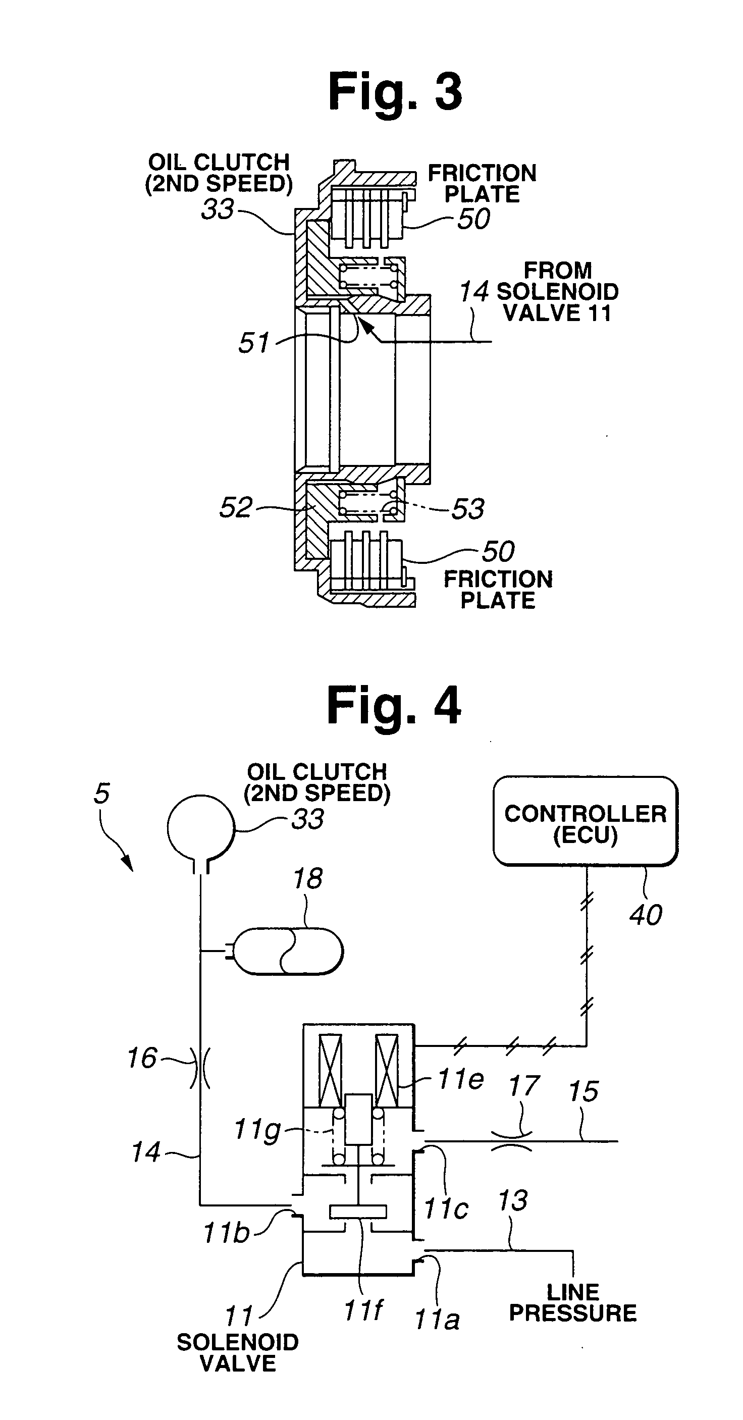
[0045] In FIG. 1, there is provided an engine 1 whose output is conveyed to a drive wheel (not shown) by way of the automatic transmission 2. The automatic transmission 2 includes a torque converter 4, a transmission mechanism 3 (planet gear), an oil pressure circuit 5, a controller 40 (ECU, controlling means) and the like. The transmission mechanism 3 includes a planet gear bringing about four forward speed gears and one backward speed gear. Also included in the transmission mechanism 3 for transmission by changing gear ratio of the planet gear are friction elements such as a multiple of oil clutches and a multiple of oil brakes.

[0046] Operation of the transmission mechanism 3 may be controlled based on a control signal from the controller 40. Herein, the controller 40 incorporates a memory {including...

second embodiment

[0133] 2. Second Embodiment

[0134] There is provided a transmission control system of the automatic transmission 2 for the vehicle, according to a second embodiment of the present invention.

[0135] According to the first embodiment, the transmission control is carried out by the driver who steps on the accelerator again "before" the actual transmission start time in the downshift with the accelerator turned off.

[0136] Contrary to the first embodiment, the transmission control according to the second embodiment is carried out by the driver who steps on the accelerator again "after" the actual transmission start time in the downshift with the accelerator turned off.

[0137] Other than the operation described above, the transmission control system according to the second embodiment is substantially the same as the transmission control system according to the first embodiment. Therefore, parts and sections substantially the same are denoted by the same numerals, and repeated descriptions ar...


PUM


Abstract

A transmission control system, includes: 1) a high speed side friction element for establishing a high speed side change gear; and 2) a low speed side friction element for establishing a low speed side change gear. After a disengagement of the high speed side friction element, the low speed side friction element makes an engagement for carrying out a downshift from the high speed side change gear to the low speed side change gear. When the downshift is carried out with an accelerator turned off, a stepping on the accelerator sensed in a period between the following times: i) a time for commanding a start of a transmission, and ii) a time for the low speed side friction element to start a conveyance of a torque, prevents a changeover to the low speed side change gear, thus keeping the high speed side change gear.

Description

[0001] 1. Field of the Invention[0002] The present invention relates to a transmission control system of an automatic transmission for a vehicle, which transmission control system carries out a downshift by changing engagement state of two friction elements.[0003] 2. Description of the Related Art[0004] Conventionally, an automatic transmission combining a torque converter and a planet gear is widely used for a vehicle. The above automatic transmission makes the following control:[0005] For carrying out a downshift (e.g., from 3rd speed to 2nd speed) in a coasting travel with an accelerator of the vehicle turned off (full closed), a 3rd speed friction element (namely, a disengagement side clutch which so far was engaged) is so controlled as to be disengaged, while a 2nd speed friction element (namely, an engagement side clutch) is so fedback gradually from a disengagement state to an engagement state. With this, the downshift to the 2nd speed is ended.[0006] Hereinabove, a driver of...

Claims


Application Information

Patent Timeline
Patent Type & Authority Applications(United States)
IPC IPC(8): B60W10/06B60W10/04B60W10/10B60W10/11B60W10/115F02D29/00F02D41/04F16H59/14F16H59/18F16H59/24F16H61/04F16H61/06F16H61/16F16H61/26F16H61/68F16H61/684F16H61/686F16H63/50
CPCB60K2741/065Y10T477/69387B60W10/11B60W30/18B60W2710/0666F16H61/061F16H61/16F16H63/502F16H2306/42F16H2306/44F16H2306/52Y10T477/638Y10T477/6939Y10T477/79Y10T477/78Y10T477/753Y10T477/693636B60W10/06B60W10/04B60W30/1819
Inventor IWAMOTO, IKUHIROHAMANO, MASAHIROUSUKI, KATSUTOSHIFURUICHI, YOICHIYAMANAKA, NOBUHIRO
Owner JATCO LTD
Why Eureka
Try Eureka