Rotational rate sensor

a sensor and rotational rate technology, applied in the direction of acceleration measurement using interia force, turn-sensitive devices, instruments, etc., can solve the problems of increasing the dynamic range requirements, increasing the noise of the sensor, and a process that is costly and often iterative as well as tedious

Inactive Publication Date: 2004-07-01
ROBERT BOSCH GMBH
View PDF6 Cites 39 Cited by
  • Summary
  • Abstract
  • Description
  • Claims
  • Application Information

AI Technical Summary

Problems solved by technology

Typical causes for this rotation are, for example, asymmetries in the sensor structure by reason of imperfections in the manufacturing process.
In the case of large quadrature signals compared to the rotational rate measuring range, this means drastically increased requirements on the dynamic range of the first signal conversion stages, and often leads to increased sensor noise.
However, the balancing (procedure) represents a costly and often iter

Method used


Image

  • Rotational rate sensor
  • Rotational rate sensor
  • Rotational rate sensor

Examples


Embodiment Construction

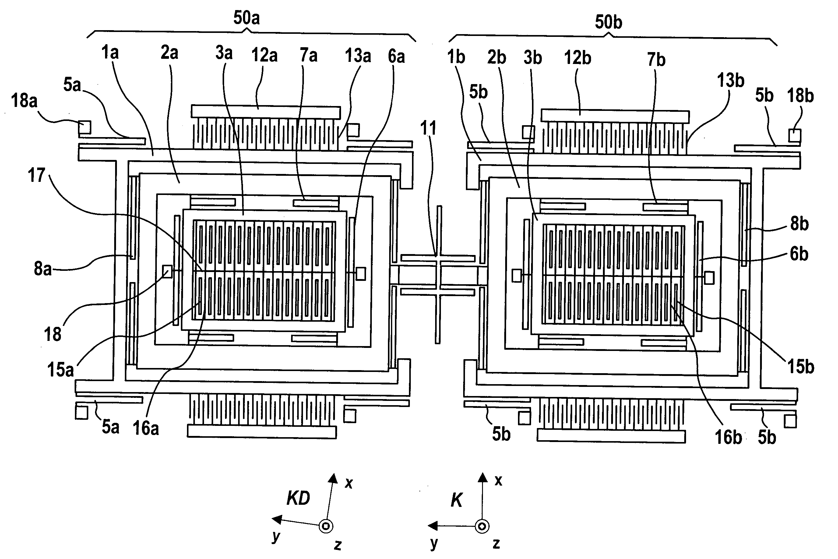
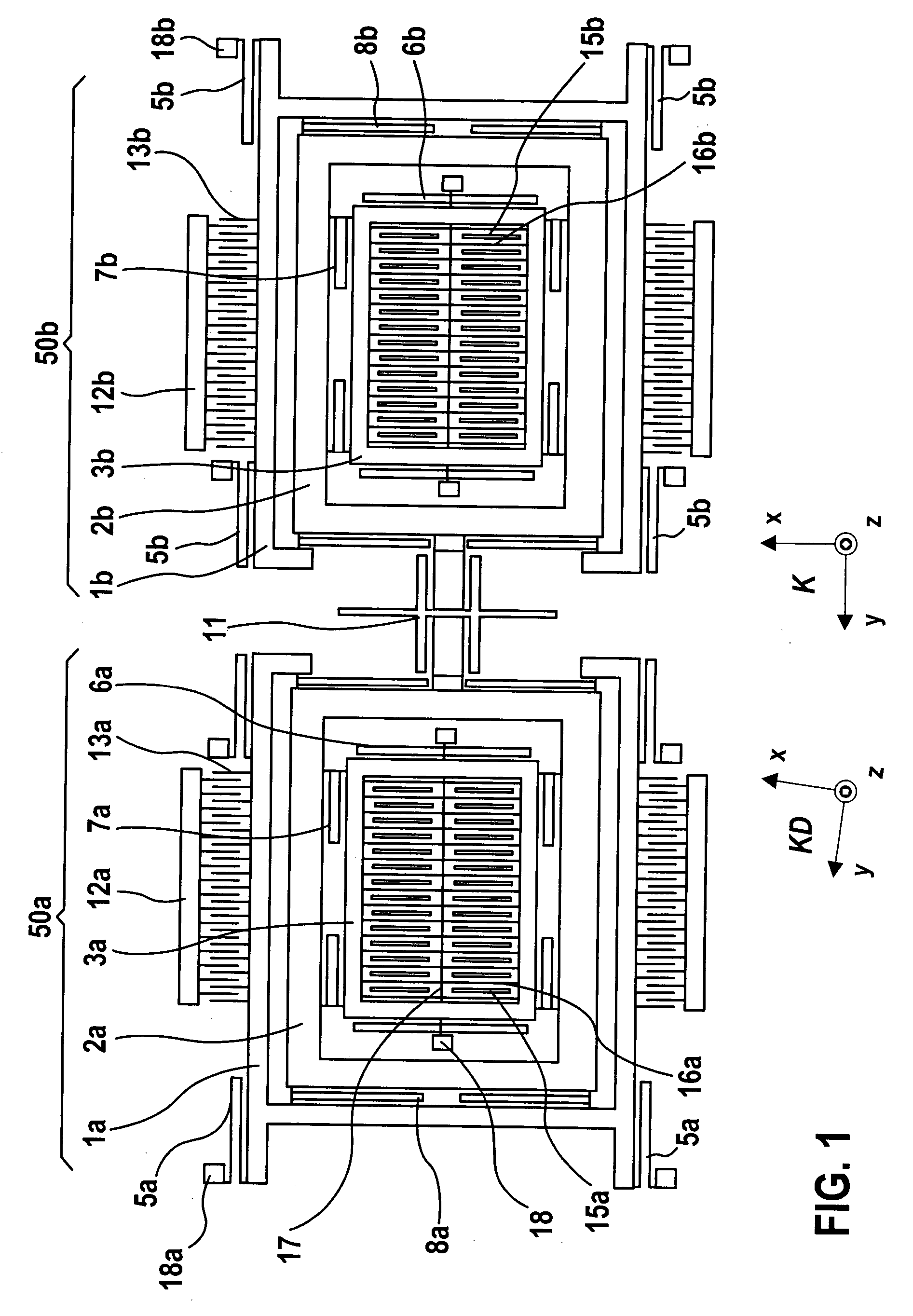
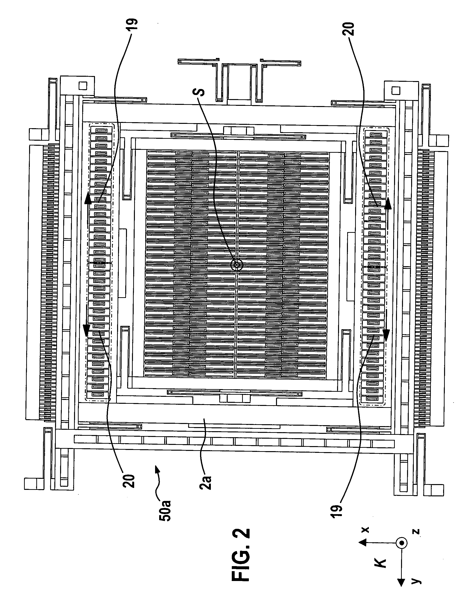
[0018] A possible embodiment of the method according to the present invention for static quadrature compensation is shown below using as the example a micromechanical rotational rate sensor. The method may be applied to a special class of rotational rate sensors. In this context, this involves linearly vibrating vibration gyroscopes. An exemplary embodiment of the present invention is explained below, first of all the essential functional components of the rotational rate sensor being briefly described in the light of the rough illustration of FIG. 1, for an understanding of the procedure of the present invention.

[0019] FIG. 1 shows the top view of the structured parts or rather, the structure of a rotational rate sensor or a rotational rate sensor element, the substrate lying under the particularly micromechanically structured structure of the rotational rate sensor not being shown, for reasons of clarity.

[0020] Silicon is preferably used as the material for the substrate and for t...


PUM


Abstract

A rotational rate sensor having a substrate and a Coriolis element is proposed, the Coriolis element being situated over a surface of a substrate; a driving arrangement being provided, by which the Coriolis element is induced to vibrations parallel to a first axis; a detection arrangement being provided, by which an excursion of the Coriolis elements is detectable on the basis of a Coriolis force in a second axis that is provided to be essentially perpendicular to the first axis; the first and second axis being parallel to the surface of the substrate; sensor elements that are designated to be at least partially movable with respect to the substrate being provided; a force-conveying arrangement being provided; the force-conveying arrangement being provided to convey a static force effect between the substrate and at least one of the sensor elements.

Description

BACKGROUND INFORMATION[0001] The present invention is based on a rotational rate sensor of the type set forth in the main claim.[0002] Linearly vibrating vibration gyroscopes are generally known. In these rotational rate sensors, parts of the sensor structure are actively set into vibration (primary vibration) in one direction, i.e. in a first axis (x axis), which is oriented parallel to a substrate surface. At an external rotational rate about a singular sensitive axis, Coriolis forces are exerted on the vibrating parts. These Coriolis forces, which vary periodically with the frequency of the primary vibration, give rise to vibrations of parts of the sensor structure (secondary vibration) that are also parallel to the substrate surface in a second direction or second axis (y axis) which is oriented perpendicularly to the x axis. Means of detection are mounted on the sensor structure which detect the secondary vibration (Coriolis measuring effect).[0003] In the lay-out of the rotati...

Claims


Application Information

Patent Timeline
IPC IPC(8): G01C19/56
CPCG01C19/5747
Inventor WILLIG, RAINERFRANZ, JOCHENKUHLMANN, BURKHARDHAUER, JORGGOMEZ, UDO-MARTINMAURER, DIETERDOERING, CHRISTIANBAUER, WOLFRAMBISCHOF, UDONEUL, REINHARDCLASSEN, JOHANNESLANG, CHRISTOPHFREY, JENS
Owner ROBERT BOSCH GMBH
Why Eureka
Try Eureka