
Laser lavelling apparatus

a laser beam and lavelling technology, applied in the direction of active open surveying means, instruments, surveying and navigation, etc., can solve the problems of lack of laser beam movement range, restricted tilt angle of such devices, and inability to project laser down the centre of the apparatus

Inactive Publication Date: 2004-07-01
CONNOLLY MICHAEL
View PDF4 Cites 26 Cited by
  • Summary
  • Abstract
  • Description
  • Claims
  • Application Information

AI Technical Summary

Benefits of technology

[0011] It will be appreciated that the laser beam can be collimated along three orthogonal axes without the need to rotate the laser assembly, head assembly or body assembly about their respective axes and therefore increased accuracy in collimation may result because any inaccuracies in rotation angles do not affect the collimation.
[0018] The base assembly may be supported on the platform through a central pivotal connection. The base levelling means preferably cooperates between the platform and the base assembly to allow adjustment of the height of the base relative to the platform in two orthogonal directions. In this way the tilt of the base, body, head and laser assemblies relative to the platform can be adjusted.
[0020] Preferably the base levelling means is positioned at or adjacent the periphery of the body, or alternatively the distance between the levelling means and the point at which the base pivots on the platform is maximum. This may allow for greater control of the adjustment than when the adjustment is made at or near the pivot point.
[0022] The first end of the head assembly may also contain a head assembly locking means for accurately locking the head assembly in 0, 90, and 180 degree positions. The head assembly locking means may include a locking wedge for engaging the head assembly and containing four radially outwardly projecting tabs spaced at 90 degree intervals at one end, with the tabs engageable in corresponding slots in a bearing block, wherein the tabs can be disengaged from the slots to allow rotation of the head assembly and re-engaged in either of the 0, 90, or 180 degree positions.

Problems solved by technology

However the tilt angle of such devices is normally restricted because the positioning of the laser head on the body results in the periphery of the body blocking the laser at certain angles.
Thus these apparatus suffer from the drawback of lack of range of movement of the laser beam and are therefore restricted to use in relatively simple marking out tasks.
Subsequently, apparatus have been developed which have two or three axes of rotation of a laser head but do not allow the laser to be projected down the centre of the apparatus.
These apparatus do however provide an increase in the degree of movement but with that increase in movement comes problems with accuracy of movement of the laser.
In this case the laser head contains a optical quality prism and a laser source and therefore the weight contained in the laser head exerts a significant load on the drive means used to rotate the head to sweep the laser.
In addition the uneven distribution of weight may result in stability problems with the apparatus.
A further problem with many of the known apparatus is that a single instrument cannot be used to perform all of the end functions required by the end user, and in those instruments that do allow more than one function, it is usually necessary to `set up` the instrument between different functions.

Method used


Image

  • Laser lavelling apparatus
  • Laser lavelling apparatus
  • Laser lavelling apparatus

Examples


Embodiment Construction

[0050] Similar reference characters indicate corresponding parts throughout the several views of the drawings.

[0051] Dimensions of certain of the parts shown in the drawings may have been modified and / or exaggerated for the purposes of clarity or illustration.

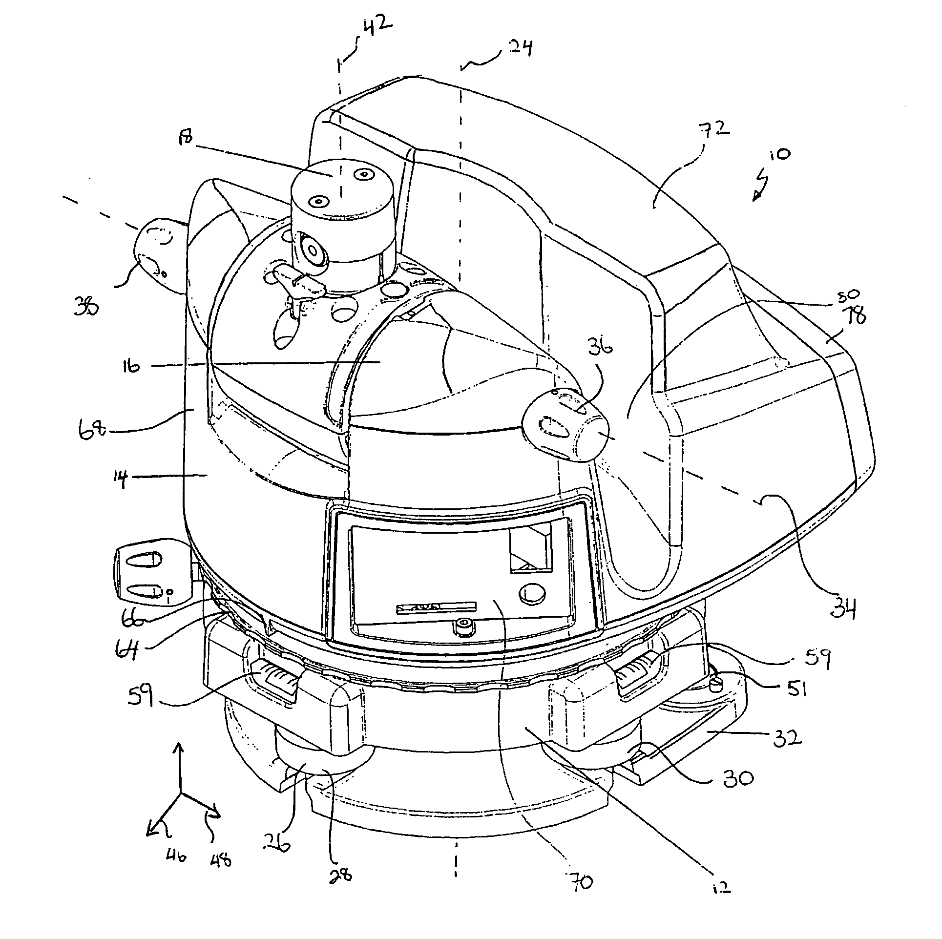
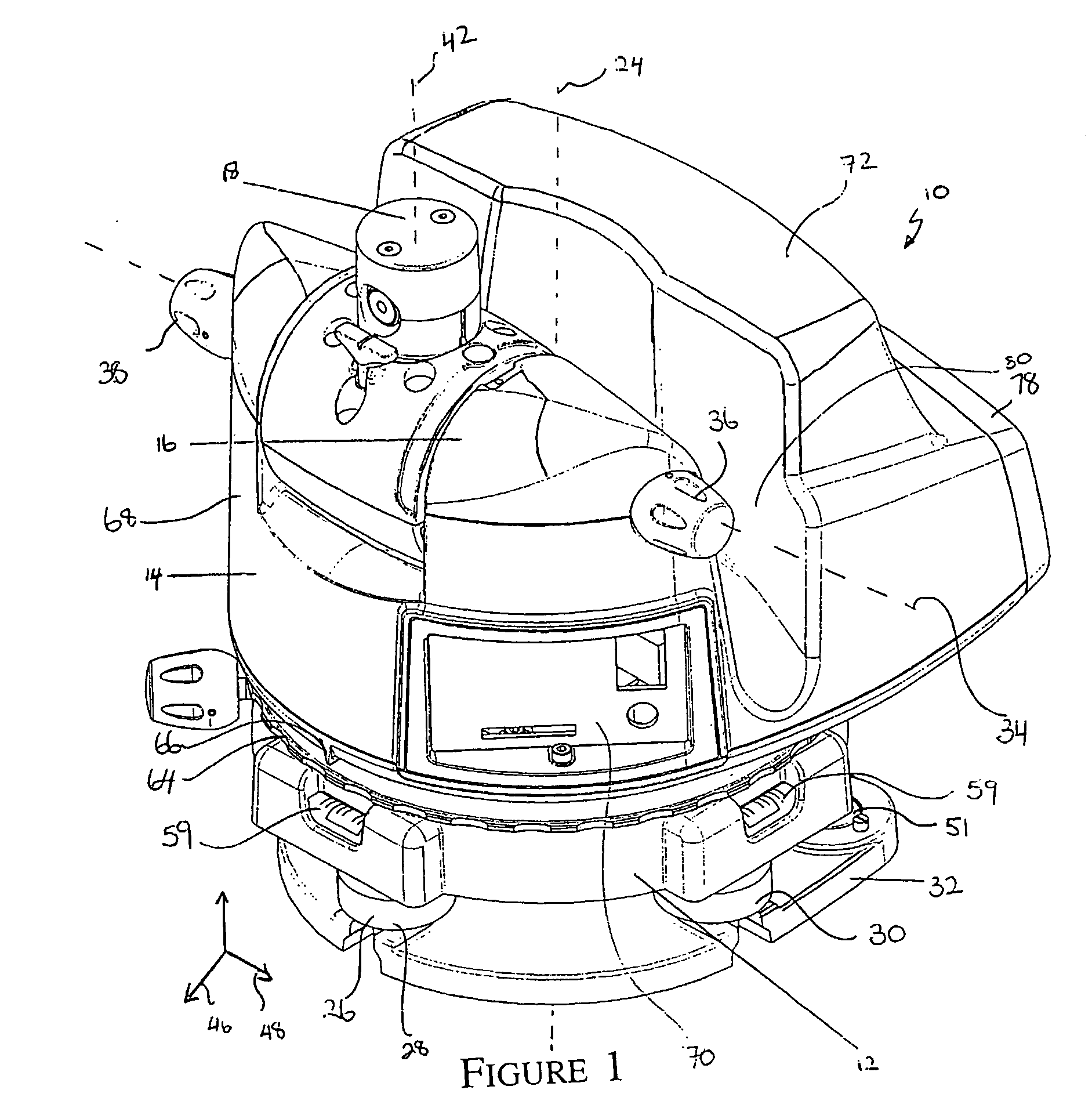
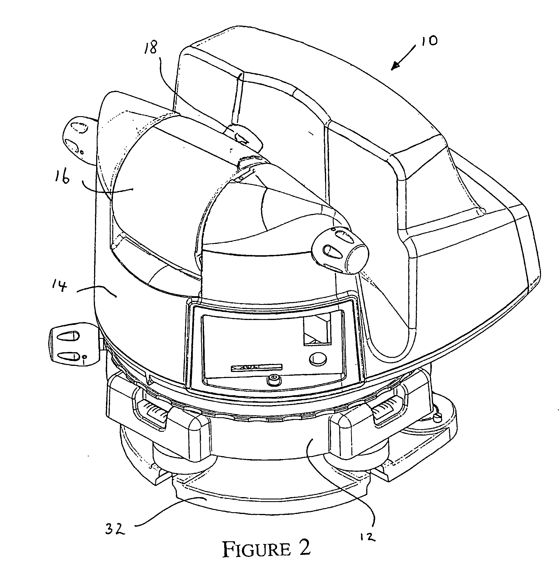
[0052] Shown is a laser levelling apparatus (10) having a base assembly (12), a body assembly (14), a head assembly (16) and a laser assembly (18). The body assembly is rotatably supported by the base assembly with a lower planar machined surface (20) of the body engaging a corresponding upper planar surface (22) of the base. The body assembly is rotatable on the base around a body assembly axis (24), which in general is shown as a vertical or near vertical axis. Body assembly levelling means (26) is used to adjust the tilt of the body and base relative to a supporting platform in two transverse directions. In the illustrated embodiments the levelling means includes two height adjustable feet (28) and (30) that are angled 90 de...


PUM


Abstract

A laser levelling apparatus includes a platform, a base assembly, a body assembly, a head assembly and a laser assembly. The body assembly is rotatable about a body axis relative to the base assembly, the head assembly is rotatably supported by the body and rotatable about a head assembly axis transverse to the body axis and the laser assembly supported by the head assembly and rotatable about a laser assembly axis which is transverse the head assembly axis. The laser assembly has a laser diode and focusing elements and laser collimator the laser beam with the laser assembly. The head assembly is mounted between a first shaft end mounted at a first position of the body and a second shaft end mounted at the second position of the body opposed to the first position. A head assembly collimator is used to adjust the axis of rotation of the head assembly. A base assembly leveller is used to adjust the level of the base relative to the platform in at least two transverse directions. The base leveller, laser collimator and head assembly collimator together and head assembly collimator together provide for collimator of the beam along three orthogonal axes.

Description

[0001] The present invention relates to laser levelling apparatus of the type commonly used in surveying, building and construction industries.[0002] Laser levelling and setting apparatus as well as other optical based apparatus such as automatic levels and theodolites are typically used in the surveying, building and construction industries to measure angles and inclination, for marking out, or to align walls and ceilings, for example.[0003] Laser levelling apparatus in particular are used to generate reference lines, for example, by sweeping a laser beam in a plane and either observing a reflection line on a surface, or alternatively using electronic detectors to detect the beam. Known devices typically project a vertical laser beam into a 45.degree. rotating prism which then reflects a horizontal sweeping beam. With these devices the beam is generally only rotated in a single plane, which is normally horizontal. With some devices it is possible to change from a horizontal to a ve...

Claims


Application Information

Patent Timeline
IPC IPC(8): G01C15/00
CPCG01C15/002
Inventor CONNOLLY, MICHAEL
Owner CONNOLLY MICHAEL
Learn More