Fiber pattern printing

a pattern printing and fiber technology, applied in the direction of catheters, packaged goods, packaging foodstuffs, etc., can solve the problem of untimely delivery of stents

Inactive Publication Date: 2004-07-01
BOSTON SCI SCIMED INC
View PDF23 Cites 36 Cited by
  • Summary
  • Abstract
  • Description
  • Claims
  • Application Information

AI Technical Summary

Problems solved by technology

This non-uniform inflation may provide for uneven delivery of the stent.

Method used


Image

  • Fiber pattern printing
  • Fiber pattern printing
  • Fiber pattern printing

Examples


Embodiment Construction

is hereafter described with specific reference being made to the drawings.

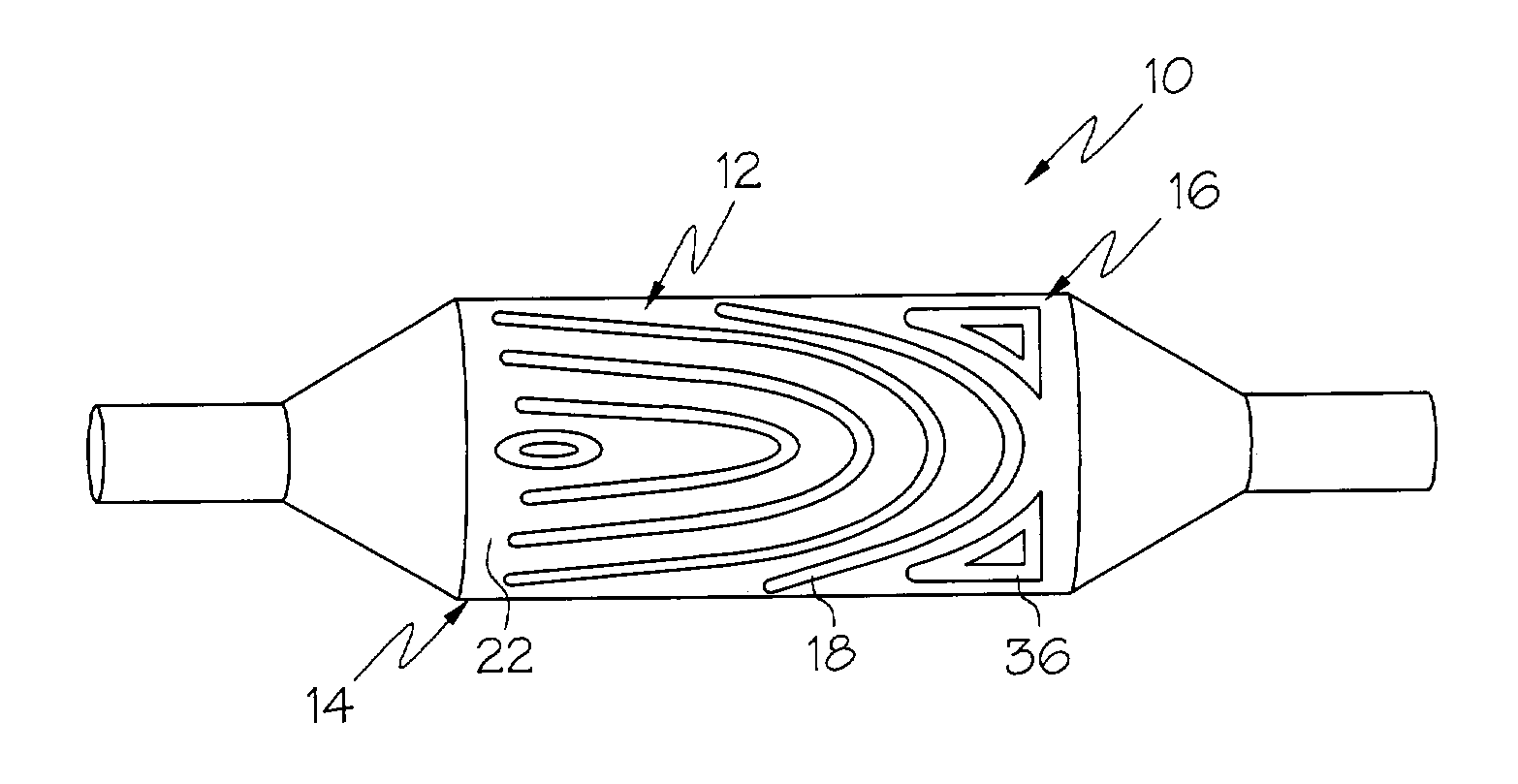
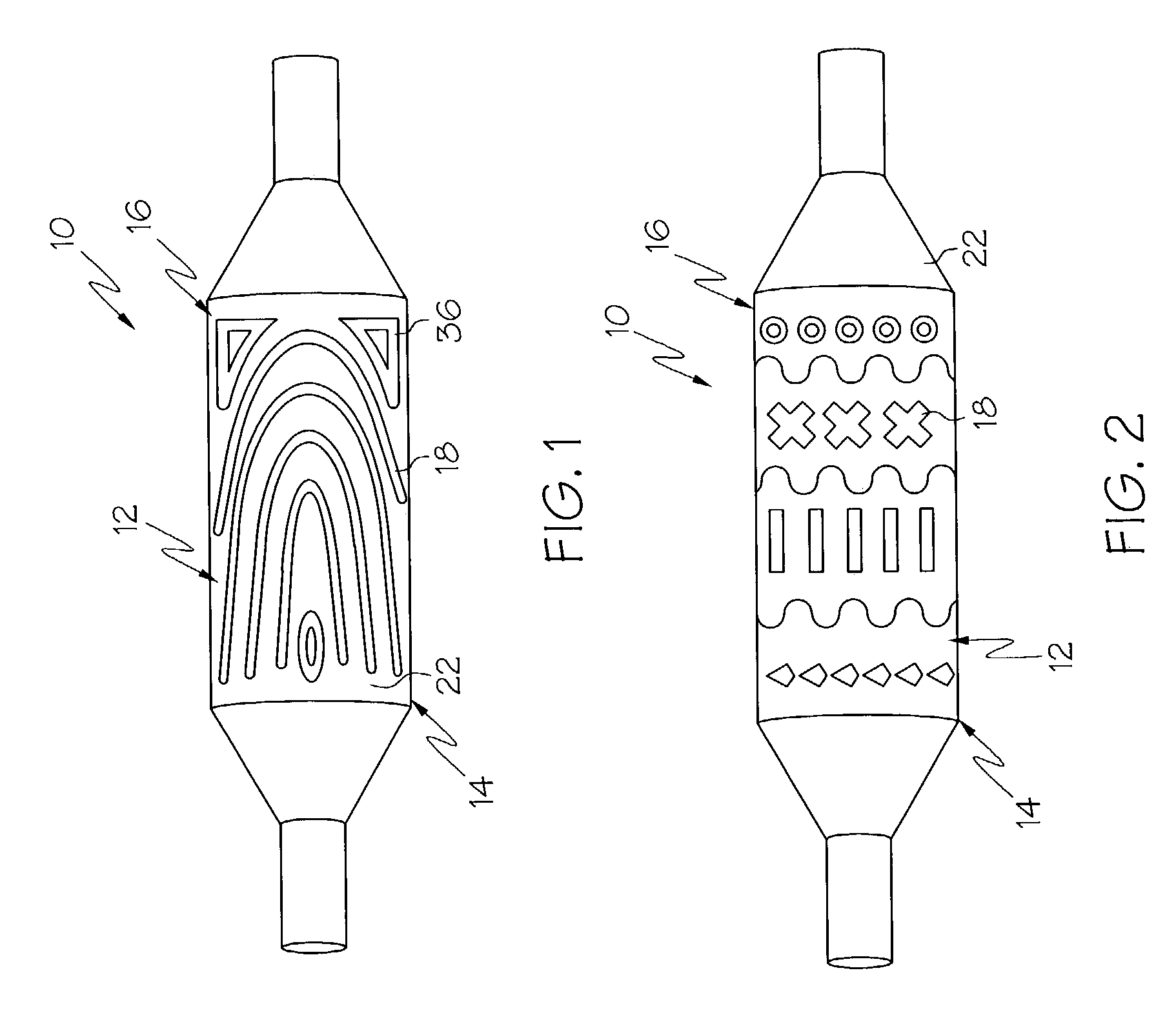
[0031] FIG. 1 is a side elevational view of an embodiment of the invention wherein a portion of a catheter is shown with one a pattern of material placed thereon.

[0032] FIG. 2 is a side elevational view of an embodiment of the invention wherein a portion of a catheter is shown with one a pattern of material placed thereon.

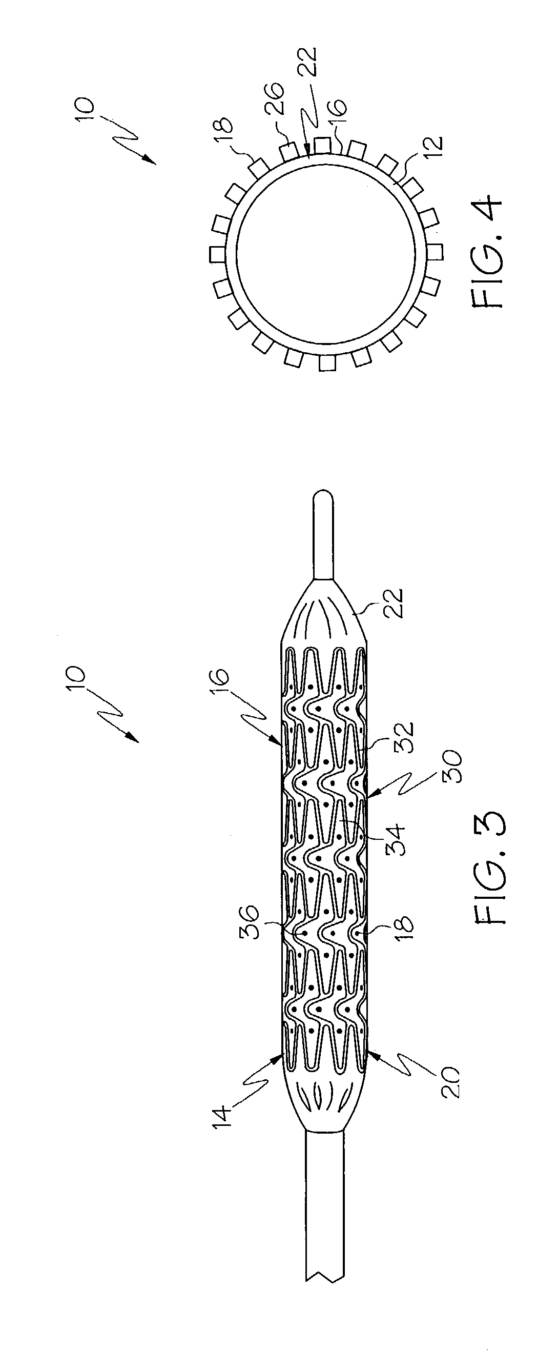
[0033] FIG. 3 is a side elevational view of an embodiment of the invention illustrating the engagement of a medical device to a catheter having a pattern of material which corresponds to openings in the framework of the medical device.

[0034] FIG. 4 is a cross-sectional view of an embodiment of the invention.

[0035] FIG. 5, labeled PRIOR ART, shows a side view of one type of known balloon during inflation.

[0036] FIG. 6 is a side view of an embodiment of the invention directed to a balloon shown during inflation.

[0037] FIG. 7 is a side view of an embodiment of the invention showing a pattern of ...


PUM

PropertyMeasurementUnit
lengthaaaaaaaaaa
pressureaaaaaaaaaa
flexibleaaaaaaaaaa

Abstract

A substantially tubular member comprises a body. The body is constructed from a first material and has an external surface. At least a portion of the external surface has a predetermined pattern of a second material deposited thereon. The predetermined pattern of the second material is deposited on the at least a portion of the external surface by one or more printing processes such as solution coating, spray coating, thermal printing, piezo jet printing, contact printing and any combination thereof.

Description

[0001] Not Applicable[0002] Not Applicable[0003] The use of catheters and medical balloons therewith, for delivery of an expandable, implantable medical device such as a stent, stent-graft, graft or vena cava filter to a desired bodily location are well known in the art. Typically, an expandable, implantable medical device such as a stent is disposed about a balloon which in turn is mounted on a catheter tube. The catheter is inserted into a bodily vessel and advanced to a desired location. The balloon is then inflated so as to expand or assist in expanding the medical device. Where the implantable medical device is self-expandable the catheter may be equipped with a medical device retaining region in addition to or in place of the medical balloon.[0004] The term `catheter` as used herein is directed to medical devices such as guide catheters, delivery catheters, balloon catheters, and portions thereof, including but not limited to inflatable members such as balloons.[0005] In deliv...

Claims


Application Information

Patent Timeline
Patent Type & Authority Applications(United States)
IPC IPC(8): A61M25/16A61M29/02
CPCA61M25/104A61M2025/1086Y10T428/1369Y10T428/1352Y10T428/139Y10T428/1362Y10T428/1393Y10T428/1372
Inventor PARSONAGE, EDWARDMILLER, PAUL J.
Owner BOSTON SCI SCIMED INC
Why Eureka
Try Eureka