
Catheter balloon with improved retention

a catheter and balloon technology, applied in the field of catheters with improved retention, can solve the problems of difficult to discern the end point of the proximal and distal cones, the proper positioning of such a medical device on the balloon catheter, and the non-uniform expansion of the medical device, so as to prevent damage to the catheter or inhibit the effect of performan

Active Publication Date: 2010-08-17
BOSTON SCI SCIMED INC
View PDF48 Cites 8 Cited by
  • Summary
  • Abstract
  • Description
  • Claims
  • Application Information

AI Technical Summary

Benefits of technology

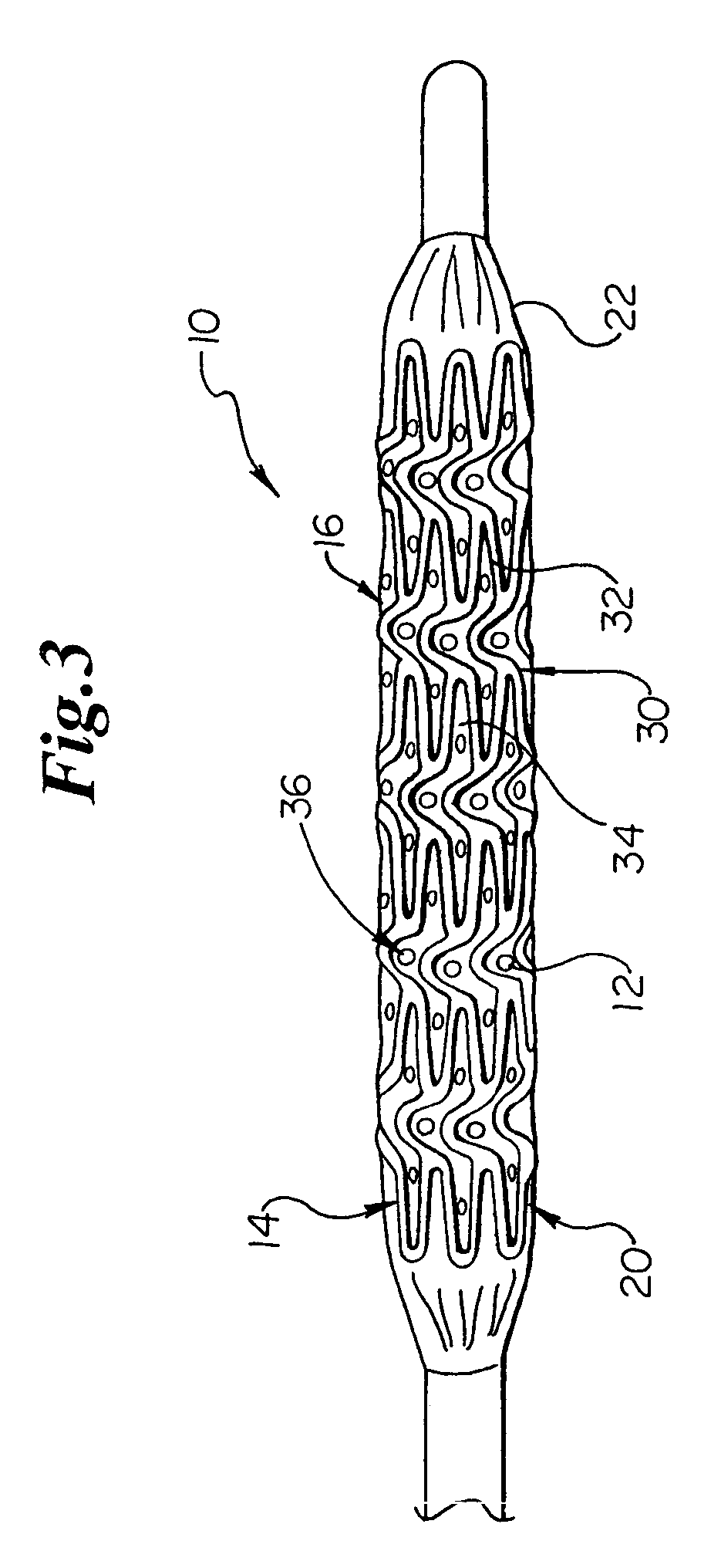
[0019]Some embodiments of the invention are directed to catheters having a textured, partially textured or otherwise marked surface which provides the catheter with improved stent retaining characteristics. The texturing or marking facilitates the positioning of an expandable, implantable medical device on the catheter and increases the securement of a stent or other expandable, implantable medical device to the catheter.
[0027]The unique patterns of surface features that may be supplied to a tubular member in accordance with the present invention allows any catheter or balloon to be readily provided with a surface suitable for engaging and / or retaining any type of stent as may be desired.
[0028]In some embodiments of the invention, the material of the tubing may be sufficiently thick or include multiple layers such that a portion of the tubing may itself be characterized as a photoresist. As a result, in some embodiments there will be no need to include an additional coating of photoresist material in order to provide the tubing with the surface features desired. In such embodiments the catheter material will be significantly think and / or diverse enough to prevent damage to the catheter or inhibit performance as a result of the photo-cross linking process.

Problems solved by technology

Failure to properly position the medical device on the balloon may result in a non-uniform expansion of the medical device.
Unfortunately, the proper positioning of such a medical device on a balloon catheter can be a challenging task because the medical device is typically mounted on an uninflated balloon.
In the uninflated state of the balloon, it is difficult to discern where the proximal and distal cones end and where the body portion of the balloon begins.
Unfortunately, typical manufacturing processes of catheters do not readily lend themselves to individualized production of different catheter types.
Providing dozens of different molds for a wide range of surface feature patterns may be cost prohibitive as well as extremely inefficient from a manufacturing perspective.

Method used


Image

  • Catheter balloon with improved retention
  • Catheter balloon with improved retention
  • Catheter balloon with improved retention

Examples


Embodiment Construction

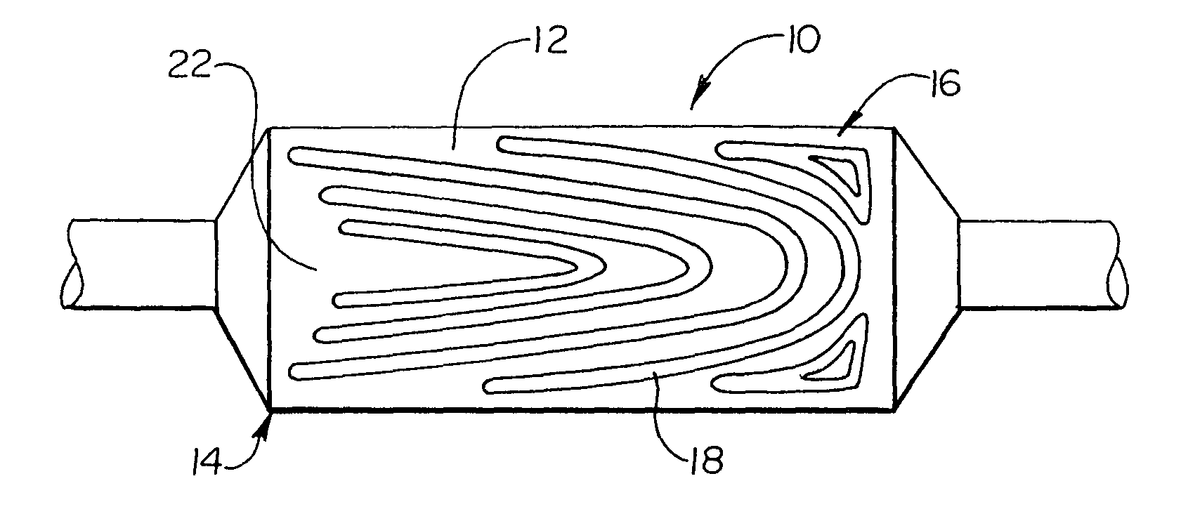
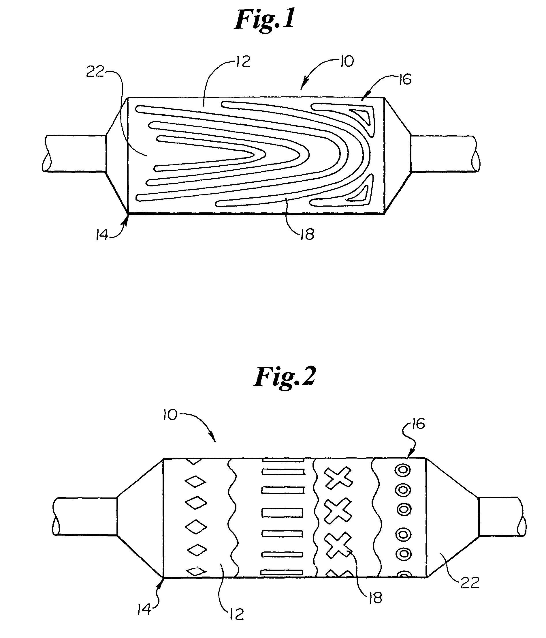
[0042]The present invention includes many different embodiments. For example, in FIGS. 1 and 2 embodiments of the invention are shown wherein different forms of medical devices, such as a catheter 10 are respectively depicted. As mentioned above, catheter 10 may be any type of elongate medical device or portion thereof, such as a balloon, capable of being inserted into a body lumen and advanced therethrough.

[0043]In the various embodiments described herein, catheter 10 may be manufactured from a tubular matrix of material 12. The catheter 10 includes a distal region 14 which has an outer surface 16 having a pattern of indented or raised secondary material 18 thereon. In at least one embodiment the secondary material 18, which comprises the pattern depicted on the catheter surface 16, is a photoresist that has been photo reacted, exposed to an etchant and rinsed in accordance with at least one method such as is described in greater detail below.

[0044]Preferably, the secondary materia...


PUM


Abstract

A catheter for delivering a medical device into a body lumen, and method for preparing said catheter, wherein the catheter comprises an elongate body, at least a portion of which defines a medical device retaining region for retaining a medical device thereon. At least a portion of the medical device retaining region comprises a predetermined pattern of material. The predetermined pattern of material is a photoresist material that may be placed on the outer surface of the catheter to modify at least one physical property of the catheter.

Description

CROSS-REFERENCE TO RELATED APPLICATIONS[0001]Not ApplicableSTATEMENT REGARDING FEDERALLY SPONSORED RESEARCH[0002]Not ApplicableBACKGROUND OF THE INVENTION[0003]Intravascular diseases are commonly treated by relatively non-invasive techniques such as PTA and PTCA. These angioplasty techniques typically involve the use of a balloon catheter. In these procedures, a balloon catheter is advanced through the vasculature of a patient such that the balloon is positioned proximate a restriction in a diseased vessel. The balloon is then inflated and the restriction in the vessel is opened. In other uses a catheter may be used to delivery an endoprosthesis such as a stent, graft, vena cava filter or other implantable device. Where an implantable device is to be delivered into a body lumen the catheter may include one or more inflatable portions or balloons.[0004]Many procedures make use of a guide catheter positioned within the vascular system of a patient. The guiding catheter assists in tran...

Claims


Application Information

Patent Timeline
IPC IPC(8): A61F2/06A61M29/00A61M25/00A61M25/10
CPCA61M25/0043A61M25/10A61M2025/1086
Inventor BURGMEIER, ROBERTGOODIN, RICHARD
Owner BOSTON SCI SCIMED INC
Learn More