Mammography apparatus

a technology of mammography and apparatus, applied in mammography, medical science, diagnostics, etc., can solve the problems of increasing the size of the mammography apparatus, not being able to detect radiation with the radiation image detector, and not accurately detecting the radiation dose through the subj

Inactive Publication Date: 2004-07-08
KONICA MINOLTA INC
View PDF3 Cites 36 Cited by
  • Summary
  • Abstract
  • Description
  • Claims
  • Application Information

AI Technical Summary

Problems solved by technology

However, in the mammography controlling the irradiation dose based on the above-mentioned phototimer, for example, if a location of the subject is deviated from a location just above the phototimer, or if the subject is not capable of being located just above the phototimer because the subject is too small, transmitted radiation dose through the subject is not detected accurately.
Therefore, in the above-mentioned cases, sometimes it is not possible to detect radiation with the radiation image detector because radiation having suitable irradiation dose is not irradiated.
However, if the distance from the radiation source to the radiation image detector becomes too large, the whole size of the mammography apparatus increases, and thereby its usability decreases.
Further, if the distance from the subject platform to the radiation image detector becomes too large compared to the distance from the radiation source to the subject platform, sharpness of an image decreases due to influence of the so-called half shadow, that is, unclearness.

Method used


Image

  • Mammography apparatus
  • Mammography apparatus
  • Mammography apparatus

Examples


Embodiment Construction

[0058] Hereinafter, an embodiment of the present invention will be explained with reference to figures.

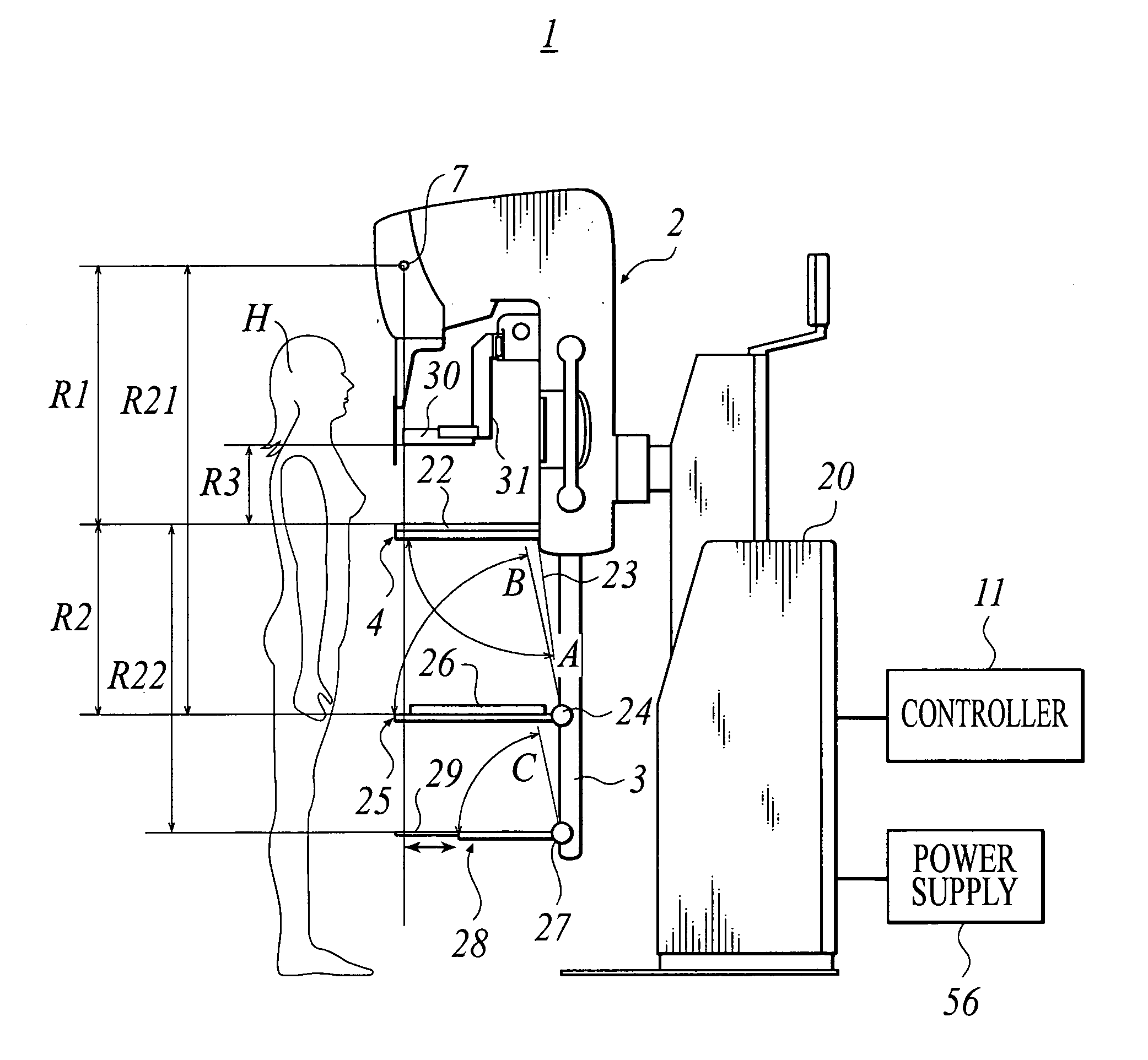
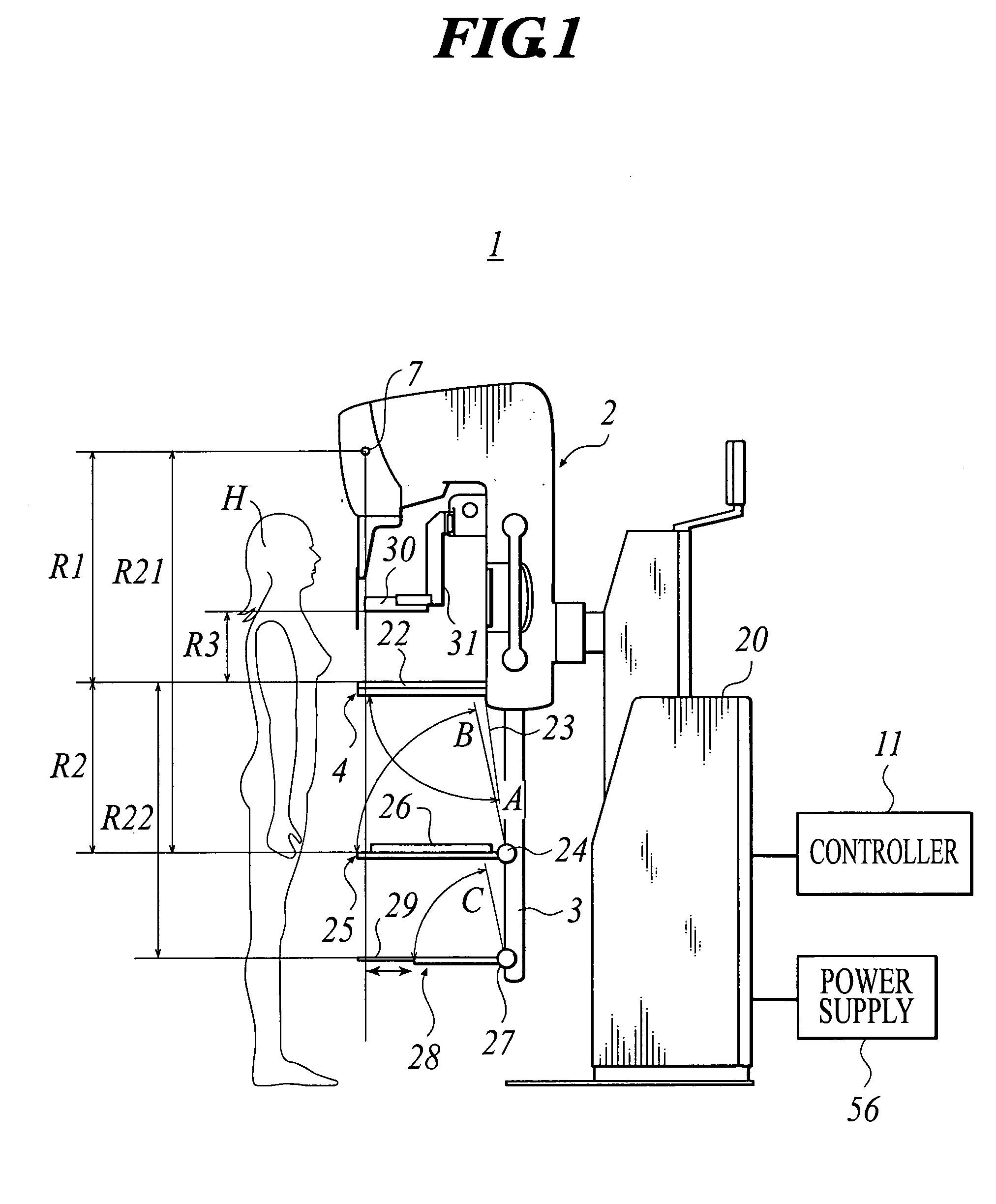
[0059] FIG. 1 is a schematic view showing main components of a mammography apparatus 1 of the present embodiment to which the present invention is applied. Here, the mammography apparatus 1 radiographs an absorption contrast image in a normal radiography mode, and radiographs a phase contrast image in a phase contrast image radiography mode.

[0060] In the mammography apparatus 1, a radiography unit 2, having a shape of a letter "7" when it is seen from its side, is placed while being supported by a support base 20 having a pillar shape.

[0061] At a lower part of the radiation unit 2, placed are a subject platform 4 projecting horizontally for supporting a subject H, and a support axis 3 projecting downwardly for supporting a radiation image detector 26 and the like. At an upper part of the radiography unit 2, placed is a radiation source 7 for irradiating radiation toward the subject...


PUM


Abstract

A mammography apparatus capable of irradiating radiation having enough irradiation dose to radiograph an image surely. The mammography apparatus has: a radiation source; a subject platform for supporting a subject so as to face the subject to the radiation source; a radiation image detector located so as to be faced to the radiation source with respect to the subject platform for detecting radiation transmitted through the subject; a controller for controlling the radiation source; wherein the controller sets an irradiation condition of the radiation to be irradiated from the radiation source based on control conditions including at least thickness of the subject and a distance from the radiation source to the subject platform.

Description

[0001] 1. Field of the Invention[0002] This invention relates to a mammography apparatus, in particular a mammography apparatus capable of radiographing a phase contrast image.[0003] 2. Description of Related Art[0004] Conventionally, as an apparatus for an image diagnosis in a medical field, a mammography apparatus is available. The mammography apparatus is to obtain radiation image information by irradiating radiation which is at a level of not harming health of an examinee, from a radiation source toward a subject, which is a mamma of the examinee, and detecting the radiation transmitted through the subject with a radiation image detector (for example, see Japanese Patent Application Publication (Unexamined) No. Tokukai 2001-238871).[0005] The mammography apparatus comprises a controller for controlling irradiation dose of radiation irradiated by the radiation source. Concretely, the controller controls irradiation dose from the radiation source based on the irradiation dose of r...

Claims


Application Information

Patent Timeline
Patent Type & Authority Applications(United States)
IPC IPC(8): A61B6/00A61B6/04
CPCA61B6/0414A61B6/484A61B6/589A61B6/542A61B6/544A61B6/502
Inventor OHARA, HIROMU
Owner KONICA MINOLTA INC
Why Eureka
Try Eureka