Control scheme for spatial and level searching of a panoramic stabilized periscope

a stabilized periscope and control scheme technology, applied in the field of automatic vision tracking system, can solve the problems of not having a platform gyroscope for correlation when the platform is used, and modern improvements have failed to control the target position in the three dimensional spatial coordinates

Inactive Publication Date: 2004-07-08
CHEN PING HO
View PDF5 Cites 14 Cited by
  • Summary
  • Abstract
  • Description
  • Claims
  • Application Information

AI Technical Summary

Problems solved by technology

Recent improvements have equipped periscopes with dual axes drive (AZ & EL), but there still exist no platform gyroscope for correlation when

Method used


Image

  • Control scheme for spatial and level searching of a panoramic stabilized periscope
  • Control scheme for spatial and level searching of a panoramic stabilized periscope
  • Control scheme for spatial and level searching of a panoramic stabilized periscope

Examples


Embodiment Construction

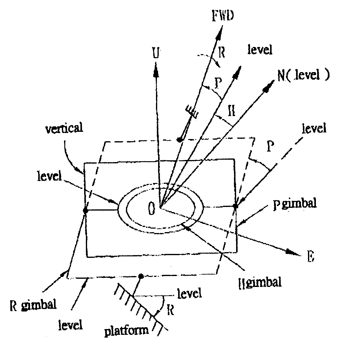
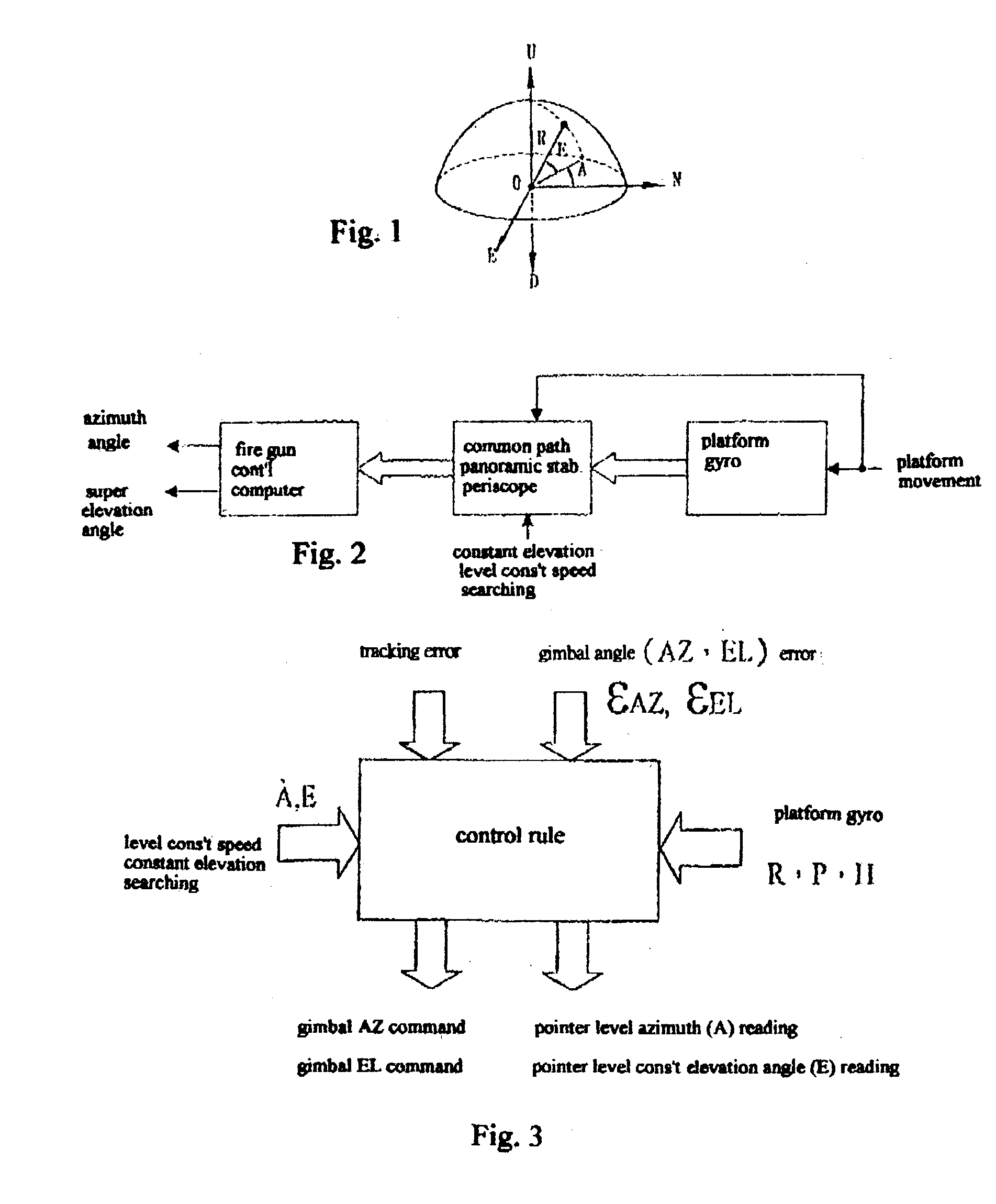
[0026] FIG. 1, shows a three dimensional spatial spherical coordinate to illustrate the target positioning in the solid spatial coordinate for a panoramic stabilized common-optical-path periscope. The bottom plane of the coordinate is at a local level; that is, composed of local north (N) and east (E) levels to form a basic plane.

[0027] Referring to FIG. 1, the right hand rule shows two possible coordinates: N E D or E,N,U coordinate. The target positioning is A ER (spherical coordinate), wherein A is the Azimuth, B is the Elevation angle, and R is the range. The searching scan type is represented by the following parameters: constant speed level scan, wherein A=constant and E=0; constant speed constant elevation angle spatial scan, wherein A=Const and E>0.

[0028] Still referring to FIG. 1, because there exist an actual pointer control error and vision tracking error of the head mirror gimbal, there is a need to precisely transform the actual pointer direction into a level pointer re...


PUM


Abstract

This invention relates to a control method for spatial and level searching applied to a panoramic stabilized periscope especially for use in military vehicles. The control method of the present invention uses platform altitude angles including heading, pitch, roll and spatial level constant elevation angle pointer vector as inputs, and periscope gimbal azimuth angle (AZ) and elevation angle (EL) command as outputs.

Description

[0001] 1. Field of the Invention[0002] The present invention relates to a control method for spatial and level searching applied to a panoramic stabilized periscope of military vehicles. More specifically, the present invention relates to an automatic vision tracking system for improving spatial and level searching control method applied to panoramic stabilized periscope of military vehicles.[0003] 2. Related Prior Art[0004] Traditional periscope head mirror of military vehicles has a single elevation axis (EL) design, and the target acquisition is based on the azimuth (AZ) of the gun turret, which is independently unable to search for panorama through its azimuth rotation, and thus unable to record and process the panorama for automatic vision tracking (AVT).[0005] Recent improvements have equipped periscopes with dual axes drive (AZ & EL), but there still exist no platform gyroscope for correlation when the platform is tilted. Therefore, modern improvements have failed to control ...

Claims


Application Information

Patent Timeline
IPC IPC(8): G01C9/00G02B27/64
CPCG02B27/648G01C9/00
Inventor CHEN, PING-HO
Owner CHEN PING HO
Why Eureka
Try Eureka