Sorter Conveyor

Inactive Publication Date: 2004-07-15
CRISPLANT
View PDF5 Cites 24 Cited by
  • Summary
  • Abstract
  • Description
  • Claims
  • Application Information

AI Technical Summary

Benefits of technology

0046] It is of importance for the efficiency of the interaction between the rotor and the stationary electric stator parts that the air gap between the two is made as small as possible. An adjustment of the position of the stator parts is only partly sufficient as a certain play must be allowed for variations between the article-supporting units due to inaccuracy of production and changes caused by wear. It is therefore, in order to minimise the air gap for each article-supporting unit, preferred that the conveyor comprises horizontal alignment

Problems solved by technology

A problem with respect to such sorter conveyors is that a drive unit must be provided for each cross-belt unit to move said belt for discharge of articles and, in case of induction of articles from the side of the sorter conveyor, also during induction of the articles.
Commonly, each cross-belt unit is provided with a separate electric motor that is expensive to provide and maintain and which requires a transfer of power to the moving part of the sorter conveyor by means of e.g. Inductive energy transfer or an electrical rail and collector shoes.
However, the cross-belt and the two biasing rollers limit the circumferential part of the reaction roller available to the stationary electric stator parts.
One solution would be to

Method used


Image

  • Sorter Conveyor
  • Sorter Conveyor
  • Sorter Conveyor

Examples


Embodiment Construction

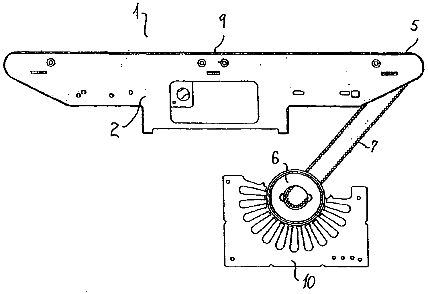
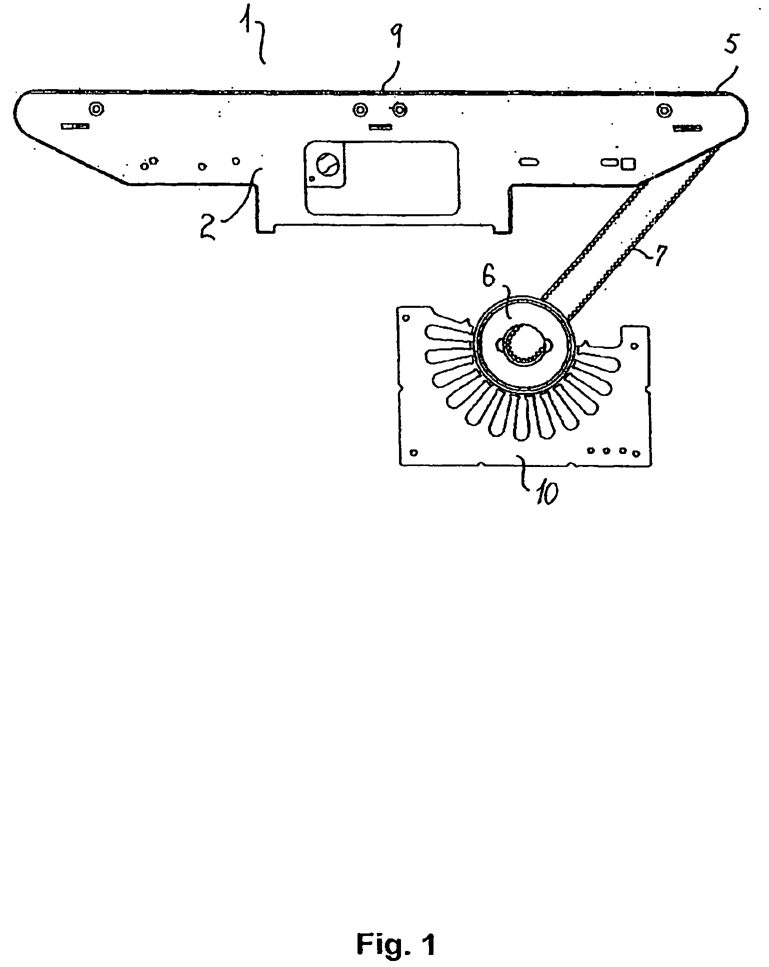
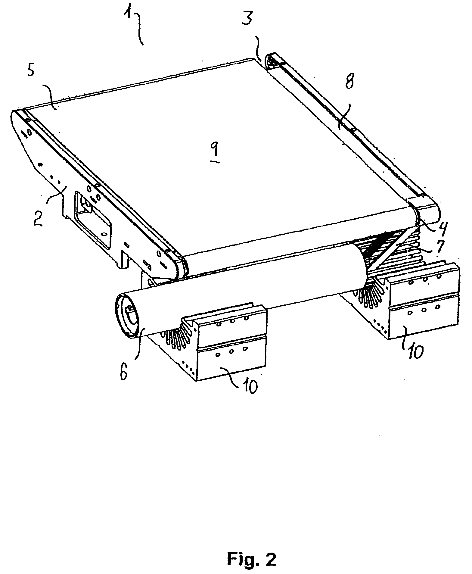
[0095] The cross-belt unit 1 shown in FIGS. 1-3 comprises a frame part 2 supporting two rollers 3, 4 around which the endless cross-belt 5 is running. One of the rollers 4 is the drive roller 4 connected to a rotor 6 by means of a toothed belt 7. The frame part 2 further carries a support plate 8 supporting the cross-belt 5 on the side opposite to the side forming the article-supporting surface 9 of the cross-belt unit 1. The rotor 6 is situated above two stationary electric stator parts 10.

[0096] The schematic view in FIG. 4 of the first embodiment of the cross-belt unit 1 may be compared to a second embodiment of a cross-belt unit 1I shown in FIGS. 5-8. In the second embodiment, the transmission means comprises an intermediate roller 11 connected at a first end to the rotor 6 by means of a first belt and at a second end thereof to the drive roller 4 by means of a second belt 7'. This configuration provides a higher freedom of design and of changing and makes variations of a given ...


PUM


Abstract

A sorter conveyor having cross-belts for supporting and discharging article is disclosed, wherein the cross-belts are driven by interaction between a rotor moving with the cross-belts and stationary electric stator parts, wherein the rotor is arranged separate from the cross-belt and is connected to a drive roller with a transmission. Further is disclosed such sorter conveyors having tilt-trays driven by interaction between rotors moving with the tilt-trays and stationary electric stator parts, as well as such sorter conveyors which are driven along the stationary track by means of stationary linear motor stator parts interacting with the reaction means. Lastly, rotors and the manufacture of such motors are disclosed.

Description

[0001] The present invention relates to sorter conveyors having cross-belts for supporting and discharging articles, wherein the cross-belts are driven by interaction between reaction means moving with the cross-belts and stationary electric stator parts, also known as Arch Induction Motors.[0002] The invention further relates to sorter conveyors having tilt-trays for supporting and discharging articles, wherein the tilting of the trays are driven by interaction between reaction means moving with the tilt-trays and stationary electric stator parts.[0003] Furthermore, the invention relates to such sorter conveyors which are driven along the stationary track by means of stationary linear motor stator parts interacting with the reaction means.[0004] Lastly, the invention relates to rotors and the manufacture of rotors suitable of being employed as said reaction means.[0005] Sorter conveyors comprising a plurality of cross-belt units for supporting articles and transport these along a s...

Claims


Application Information

Patent Timeline
IPC IPC(8): B65G17/34B65G23/23B65G47/10B65G47/96
CPCB65G17/345B65G23/23B65G2207/18B65G47/962B65G2201/02B65G47/96
Inventor MILLER, HENRIKPEDERSEN, JOHN NYMANNSORENSEN, DENNISJOCHUMSEN, HANS HENRIKMADSEN, THOMAS SCHMIDT
Owner CRISPLANT
Why Eureka
Try Eureka