Refractometer

Inactive Publication Date: 2004-07-29
ATAGO
View PDF18 Cites 25 Cited by
  • Summary
  • Abstract
  • Description
  • Claims
  • Application Information

AI Technical Summary

Problems solved by technology

There is a problem however as such optical systems require a plurality of optical elements and therefore incur high production costs.
Further the elements used for construction that contain the optical elements must be arranged separately with respect to each other and therefore require very accurate positioning further contributing toward high production costs.
It is difficult to remove the sample material applied to the sample stage of a refractometer according to the prior art however, when the sample measured is a paste like substance such as starchy syrup or the like.
Wiping away previous sample material takes time causing a problem of reducing the efficiency of measuring operations.
Further, when the wiping action to remove sample material is repeated many times the sample stage 114 easily suffers abrasions.
A problem affecting refractometers used to measure highly corrosive sample s

Method used


Image

  • Refractometer
  • Refractometer
  • Refractometer

Examples


Example

[0179] In order to verify the effects of the coating 34 of the refractometer 10 according to the embodiments of this invention a refractometer 10 was produced for experimental purposes and subject to experiments designed to compare performance with a conventional refractometer.

[0180] A refractometer using a sample stage made from SUS316 was used as an example of prior art technology. For the experimental example a composite coating 34 was formed over the external face of a sample stage the same as that of the conventional refractometer. More specifically, the composition of the coating 34 of this experimental example comprised Ni: 82-84 wt %, P: 8-10 wt %, PTFE: 20-26 vol %. The diameter of the PTFE particles included in this coating 34 was 0.2-0.3 .mu.m.

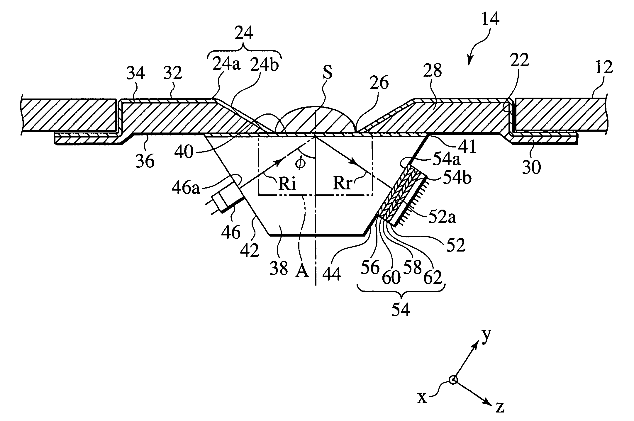
[0181] During the comparative experiment, each type of sample was dropped on to a cone shaped face 24b of a sample guide face 24 surrounding a interface surface 40 and a comparison was made of how well each of these samples slipped ...


PUM


Abstract

A refractometer for measuring refractive index of a sample comprising a prism having an interface contacting the sample, a light source that radiates light towards the interface from an entrance face of the prism, and a photoelectric sensor for receiving light reflected at the interface and directed outward from an exit face of the prism. The light source and the photoelectric sensor are secured to the prism. The refractometer comprises a sample stage arranged surrounding the interface surface. This sample stage provides a non-adhesive coating formed on the surface thereof. The refractometer comprises filter means arranged between the interface surface and the photoelectric sensor. This filter means includes a wavelength filter that selectively allows transmission of light having a wavelength within a prescribed region, including a wavelength of light of the light source.

Description

[0001] This application claims benefit of priority to Japanese Patent Application No. 2002-315814 filed on Oct. 30, 2002, the entire contents of which are incorporated by reference herein.[0002] 1. Field of the Invention[0003] This invention relates to a refractometer used for measuring sugar concentration or density in a solution.[0004] 2. Description of Relevant Art[0005] Refractometers used to measure sugar concentration or density in a solution by directing light on the boundary interface of a sample and a prism then detecting light reflected at the interface using a photoelectric sensor and measuring refractive index (sugar concentration or density) in the sample from the signal output by the photoelectric sensor are well-known. Measurements conducted using a refractometer operate on the principle that the critical angle of incidence at which total reflection occurs at the interface of a prism and a sample is dependent on refractive index of the sample.[0006] A refractometer ac...

Claims


Application Information

Patent Timeline
IPC IPC(8): G01N21/43
CPCG01N2021/435G01N21/43
Inventor NAKAJIMA, YOSHINORIAMAMIYA, HIDEYUKIOSAWA, MASAKISEKIGUCHI, KIMINORI
Owner ATAGO
Why Eureka
Try Eureka