Cornering power control device and method

Active Publication Date: 2004-08-19
SUBARU CORP
View PDF1 Cites 19 Cited by
  • Summary
  • Abstract
  • Description
  • Claims
  • Application Information

AI Technical Summary

Problems solved by technology

The problem is that, even if the wheel friction force utilization ratio is brought closer to the target wheel friction force utilization ratio, in view of the cornering power, the cornering power at this time may not

Method used


Image

  • Cornering power control device and method
  • Cornering power control device and method
  • Cornering power control device and method

Examples


Embodiment Construction

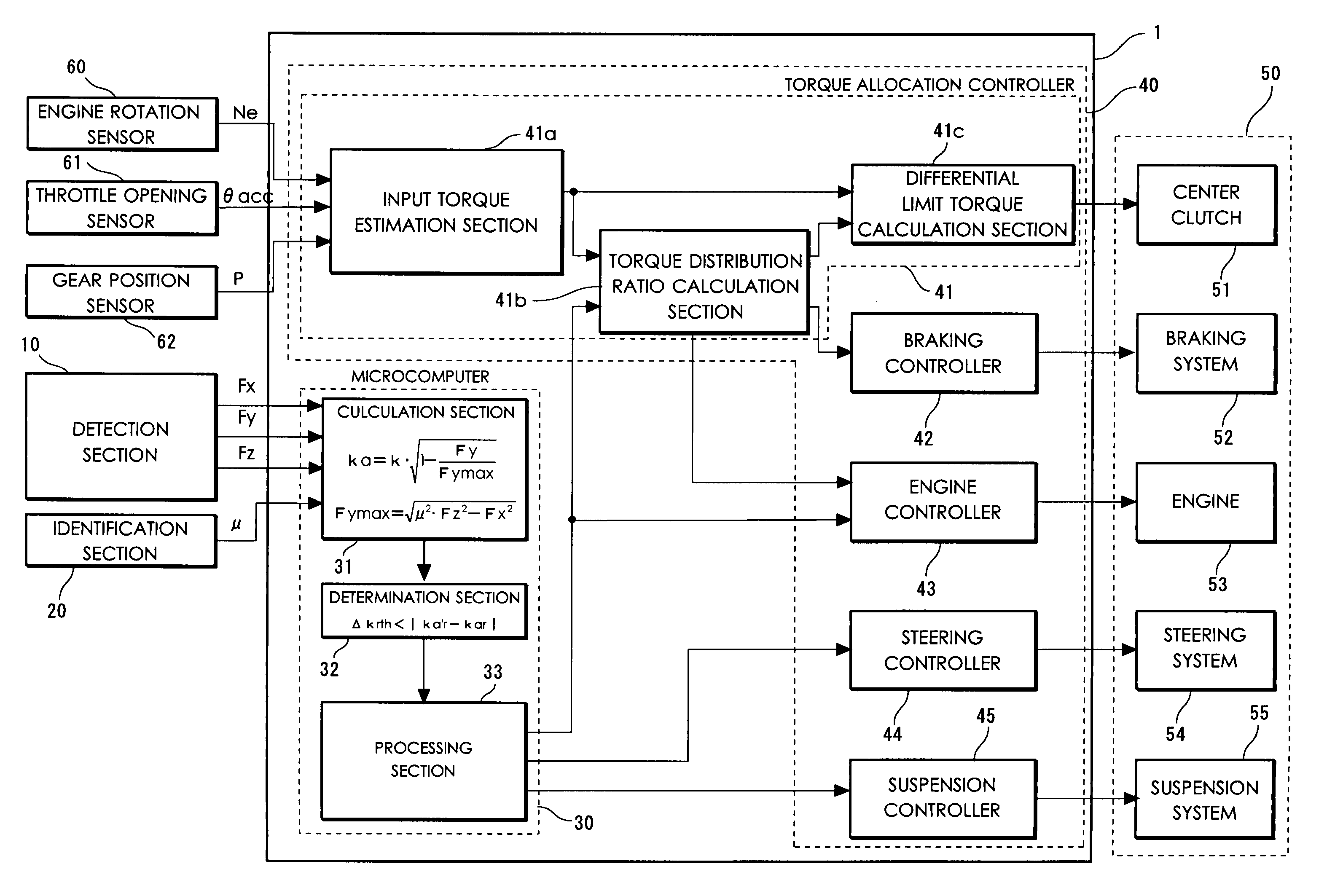
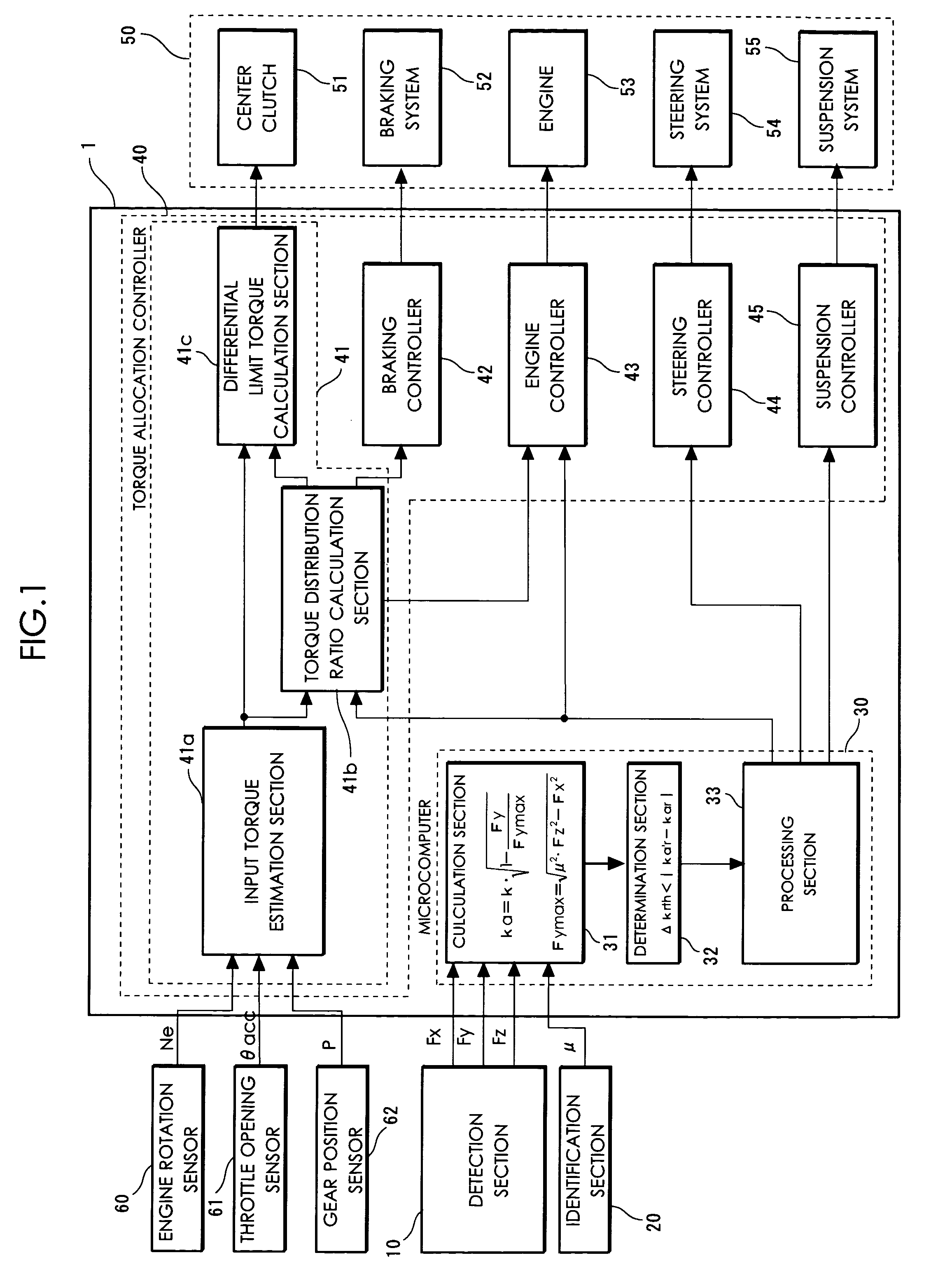
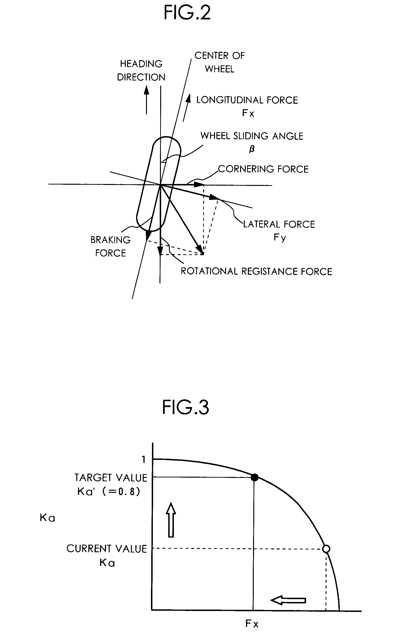
[0016] FIG. 1 is a block diagram showing the entire structure of a cornering power control device of the present embodiment. This cornering power control device 1is applied to a vehicle having a plurality of wheels (exemplarily shown in the present embodiment is a four-wheel-drive vehicle) to control the kinetic state thereof. The control device 1 calculates a cornering power Ka for the wheels, i.e., each of the four wheels in this embodiment. This calculation is made based on a longitudinal force Fx, a lateral force Fy, and a vertical force Fz, each of which is exerted on the wheel, and a friction coefficient .mu. between the wheel and the road surface. Using a current value Ka of the cornering power and a target cornering power Ka' as determination factors, the control device 1 changes the action forces exerted on the wheel. The kinetic state of the vehicle is controlled in such a manner that the current cornering power ka is brought closer to the target cornering power Ka' throug...


PUM


Abstract

To provide a new vehicle control technique, a calculation section calculates a cornering power ka using the detected longitudinal force Fx, lateral force Fy, and vertical force Fz, and the identified friction coefficient mu. This calculation is made based on the correlation between a slip angle beta of the wheels and the lateral force Fy. Based on thus calculated cornering power ka and a target cornering power ka' required for the wheels, a processing section determines a change amount for changing at least one action force out of the longitudinal force Fx, the lateral force Fy, and the vertical force Fz, all acting on the wheels. Based on thus determined change amount, a control section controls at least one action force out of the longitudinal force Fx, the lateral force Fy, and the vertical force Fz, all acting on the wheels.

Description

[0001] 1. Field of the Invention[0002] The present invention relates to a cornering power control device and a method for controlling a cornering power of a wheel and, more specifically, to vehicle control under which the kinetic state of a vehicle is controlled through control over the cornering power.[0003] 2. Description of the Related Art[0004] A vehicle control technology has been conventionally known for controlling the kinetic state of a vehicle. Exemplarily applied thereto is a technique of controlling a driving / braking torque to be exerted on wheels, or controlling the suspension property of the wheels. With the vehicle control technology, exemplarily in such a driving condition as cornering, the steerbility and stability are improved through optimal control applied to the kinetic state of the vehicle. Such a technology includes a vehicle control device for controlling the kinetic state of the vehicle by using a wheel friction force utilization ration(refer to Japanese Pate...

Claims


Application Information

Patent Timeline
IPC IPC(8): B60G17/015B60G17/016B60G17/0195B60K17/348B60K23/08B60R16/02B60T8/172B60T8/1755B60T8/1763B60T8/1764B60W10/00B60W10/04B60W10/06B60W10/10B60W10/18B60W10/184B60W10/20B60W10/22B60W30/02B60W30/045B60W40/10B62D6/00B62D6/04B62D137/00F16H61/66
CPCB60G17/0162B62D6/04B60G17/0195B60G2400/302B60G2400/33B60G2400/38B60G2400/64B60G2400/822B60G2401/12B60G2800/213B60G2800/214B60G2800/215B60G2800/915B60G2800/922B60G2800/952B60G2800/96B60G2800/97B60K23/0808B60K2741/283B60T8/172B60T8/17552B60T2230/02B60T2240/03B60W10/06B60W10/12B60W10/18B60W30/02B60W30/045B60W40/064B60W40/101B60W2420/22B60W2530/20B60W2550/148B60G17/0164B60W30/18145B60W2552/40
Inventor KOGURE, MASARUHIWATASHI, YUTAKAMATSUNO, KOJI
Owner SUBARU CORP
Why Eureka
Try Eureka