Micro chaotic mixer

a mixer and chaotic technology, applied in the field of micro mixers, can solve the problems of large time cost, change in relative magnitude of various forces involved in the analytical system, and large change in viscosity, and achieve the effect of simple construction and easy integration into any microdevi

Inactive Publication Date: 2005-06-07
UNIVERSTIY OF CALIFORNIA
View PDF16 Cites 19 Cited by
  • Summary
  • Abstract
  • Description
  • Claims
  • Application Information

AI Technical Summary

Benefits of technology

[0009]The present invention provides an improved micro mixer which obviates for practical purposes the above mentio

Problems solved by technology

However, scaling down analytical systems results in changes to the relative magnitudes of various forces involved in the analytical system.
In micro scale devices, viscous effects greatly diminish fast mixing.
However, this mechanism results in a large time cos

Method used


Image

  • Micro chaotic mixer
  • Micro chaotic mixer
  • Micro chaotic mixer

Examples


Embodiment Construction

[0025]In the following description of the preferred embodiments reference is made to the accompanying drawings which form the part thereof, and in which are shown by way of illustration specific embodiments in which the invention can be practiced. It is to be understood that other embodiments can be utilized and structural and functional changes can be made without departing from the scope of the present invention.

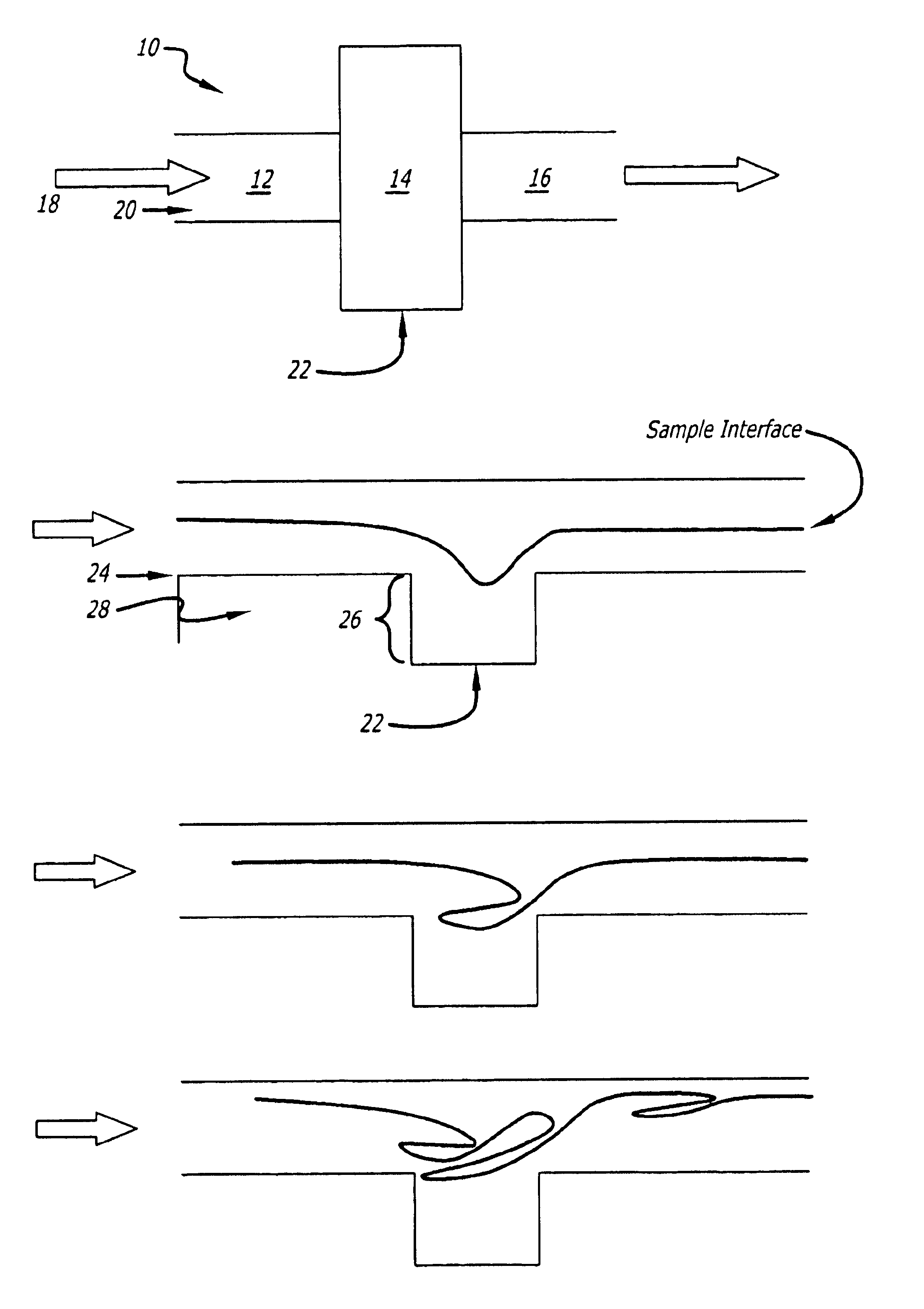
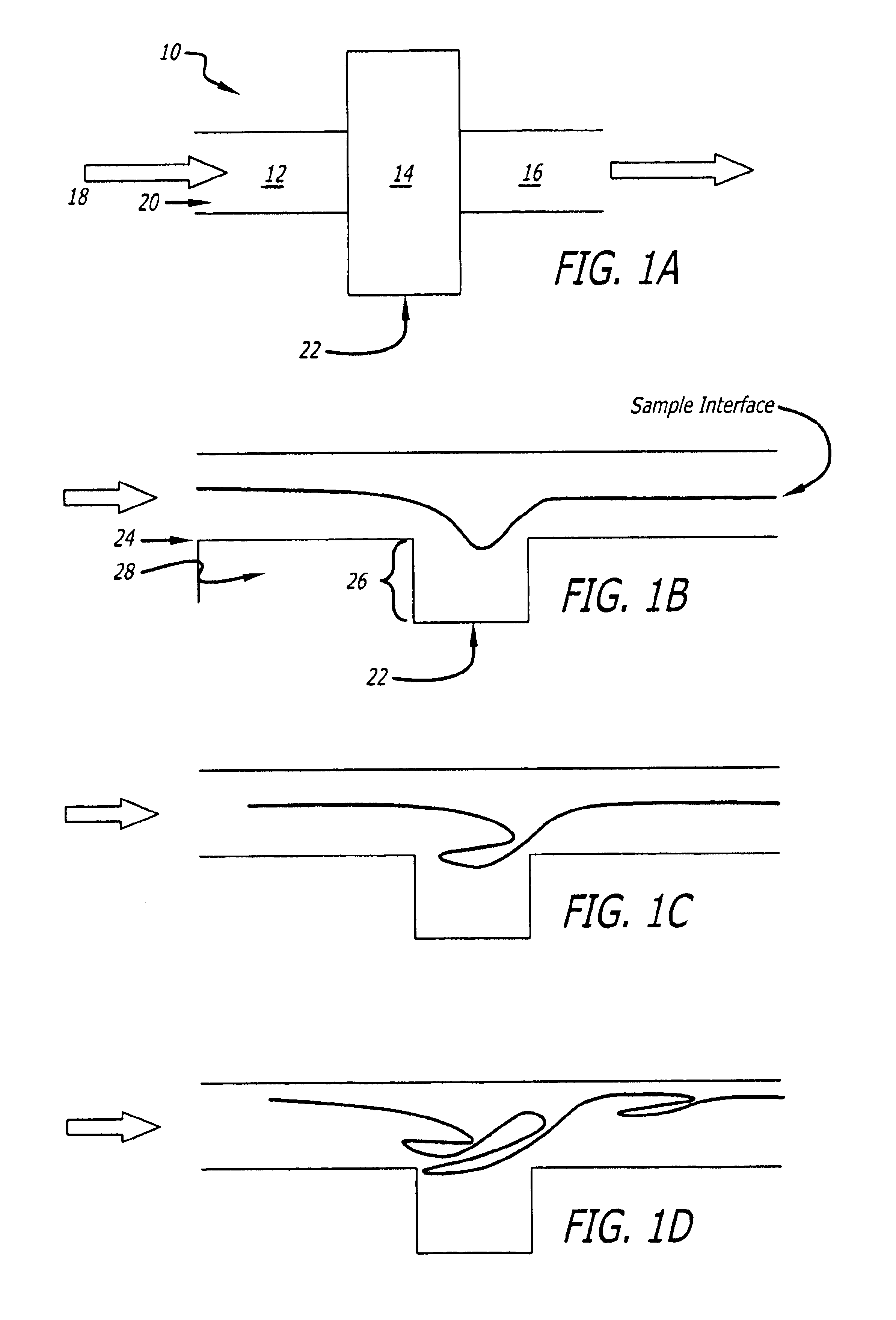
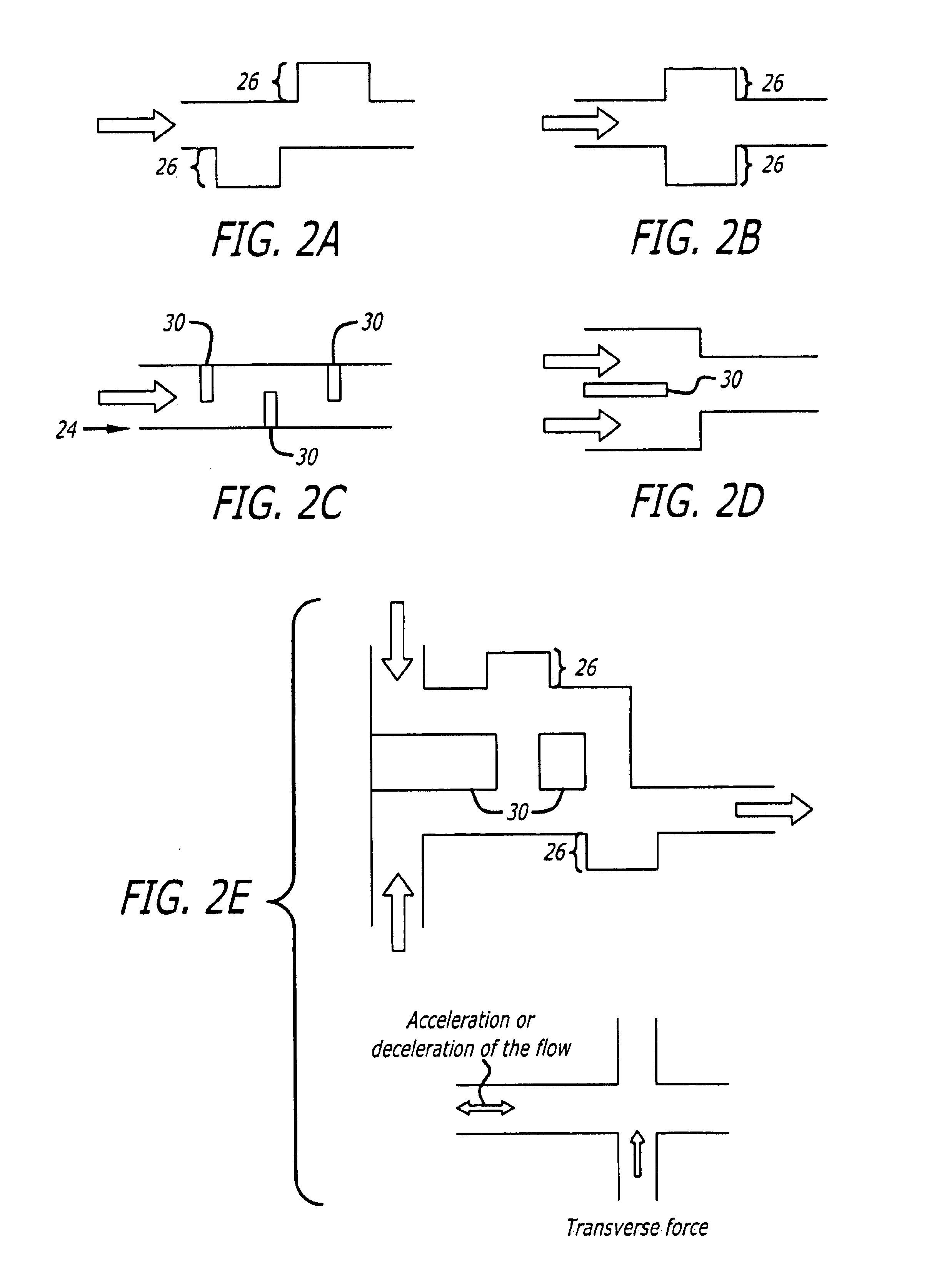
[0026]The micro mixer includes at least one means for exerting a time-varying force field upon sample components within it. The amplitude, the direction or more generally any of the parameters defining the force field upon the sample components can be modified with time. The means for exerting a time-varying force field upon the sample components can be produced by any one of: electrical fields (which can induce different electrokinetic forces on samples, such as dielectrophoresis, electrophoresis, electro-osmosis), magnetic fields, mechanical fields (such as hydrodynamic ...


PUM

PropertyMeasurementUnit
Angleaaaaaaaaaa
Electric potential / voltageaaaaaaaaaa
Pressureaaaaaaaaaa

Abstract

A micro mixer for use in a microdevice which utilizes time-varying force fields to induce bulk fluid and/or sample component motion leading to homogenization of sample components. Time-varying force fields employed includes at least one of a physical displacement field, electrical field, pressure field or magnetic field to generate transverse forces which induce the mixing of samples within the micro mixer.

Description

[0001]This appilcation claims priority to the provisional application with Ser. No. 60 / 224,292 and having a filing date of Aug. 10, 2000.[0002]This invention was made with Government support under DARPA Contract No. N66001-96-C-83632, maniged by the Department of Navy. The Government has certain rights to this invention.BACKGROUND OF THE INVENTION[0003]1. Field of the Invention[0004]This invention relates in general to micro mixers, and more specifically to micro mixers utilizing time-varying force fields to induce bulk fluid and / or sample component motion leading to homogenization of sample components.[0005]2. Description of Related Art[0006]Nano / Micro (“micro”) devices have generally been developed to improve the speed, accuracy and cost efficiency of analytical methods for chemical, biological, engineering or medical applications. However, scaling down analytical systems results in changes to the relative magnitudes of various forces involved in the analytical system. Therefore, ...

Claims


Application Information

Patent Timeline
IPC IPC(8): B01F13/00B01F5/06
CPCB01F5/0618B01F5/0646B01F5/065B01F5/0654B01F5/0655B01F13/0005B01F13/0006B01F13/0076B01F13/0077B01F13/0001Y10S366/01Y10S366/02B01F25/4316B01F25/433B01F25/4333B01F25/4337B01F25/4338B01F33/05B01F33/052B01F33/053B01F33/3031B01F33/3032
Inventor HO, CHIH-MINGTABELING, PATRICKLEE, YI-KUENDEVAL, JOANNE HELENE
Owner UNIVERSTIY OF CALIFORNIA
Why Eureka
Try Eureka