Air conditioner for vehicle

Inactive Publication Date: 2004-09-09
DENSO CORP
View PDF7 Cites 13 Cited by
  • Summary
  • Abstract
  • Description
  • Claims
  • Application Information

AI Technical Summary

Problems solved by technology

However, it is not enough to reduce the temperature of the evaporator immediately.
However

Method used


Image

  • Air conditioner for vehicle
  • Air conditioner for vehicle
  • Air conditioner for vehicle

Examples


first embodiment

[0029] (First Embodiment)

[0030] The first embodiment of the present invention will be now described with reference to FIGS. 1-4.

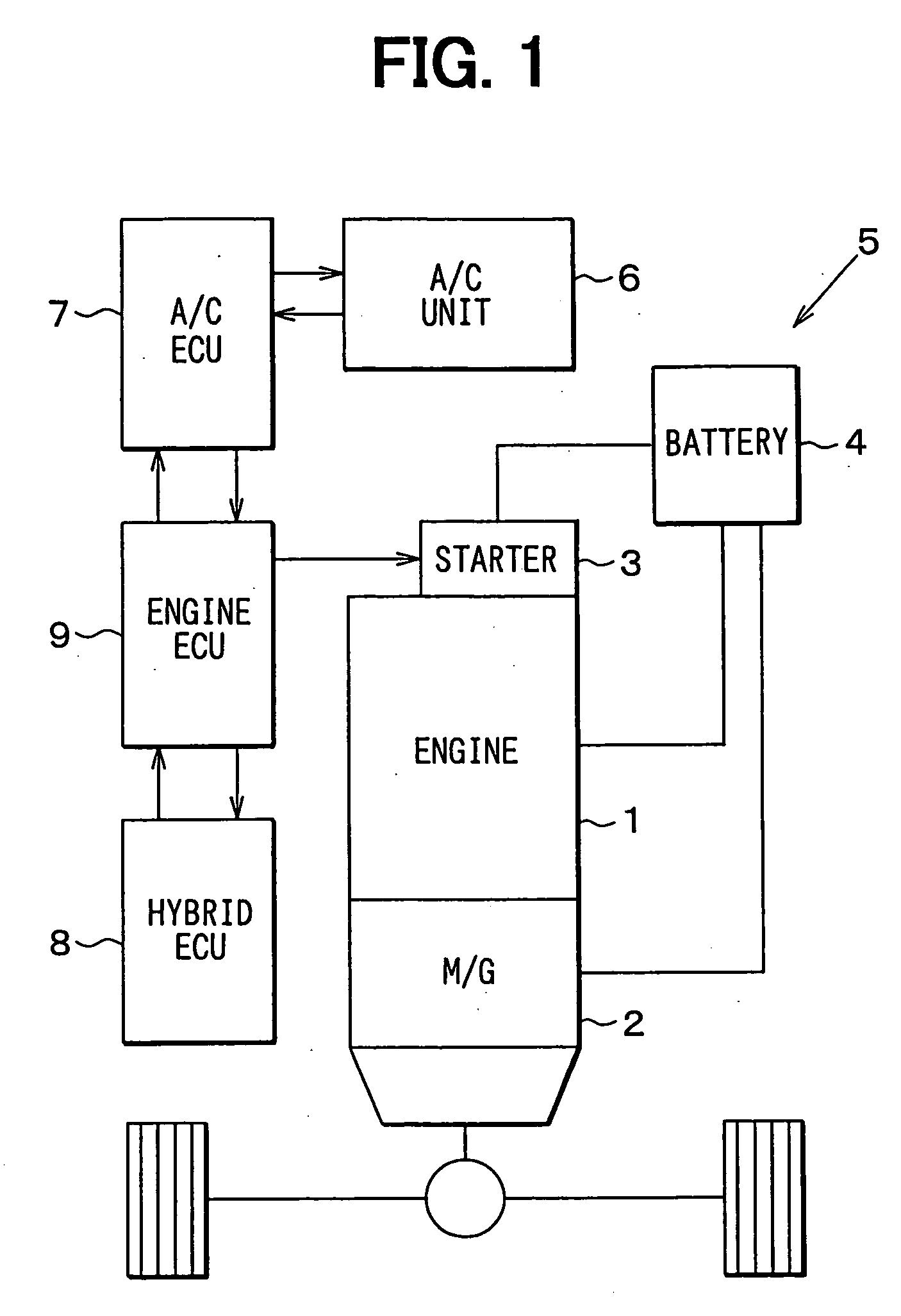
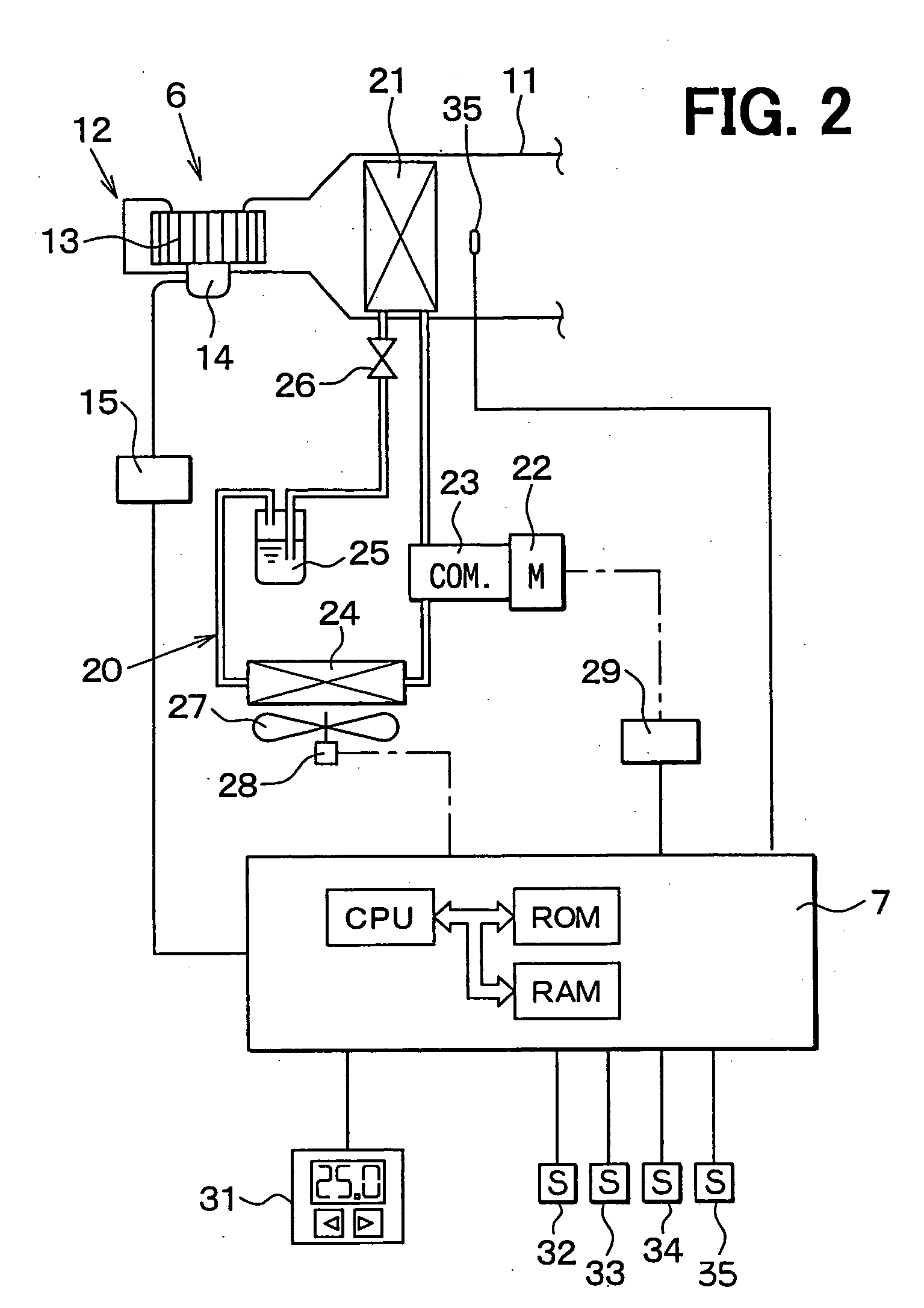
[0031] In the first embodiment, an air conditioner for a hybrid vehicle is an automatic air conditioner which automatically controls a temperature in a passenger compartment at a set temperature. Specifically, this automatic air conditioner controls actuators in an air-conditioning unit 6 for air-conditioning the passenger compartment of a hybrid vehicle 5, by using an air-conditioning electronic control unit (ECU) 7.

[0032] In addition to the air-conditioning unit 6, various devices, such as a driving engine 1, a motor generator 2, an engine starter 3 and a vehicle battery 4 are also mounted in the hybrid vehicle 5. The driving engine 1 is an engine for driving the hybrid vehicle 5. The motor generator 2 functions as both an electronic motor and an electronic generator. The engine starter 3 includes a starting motor for starting the driving engine 1 and an ...

second embodiment

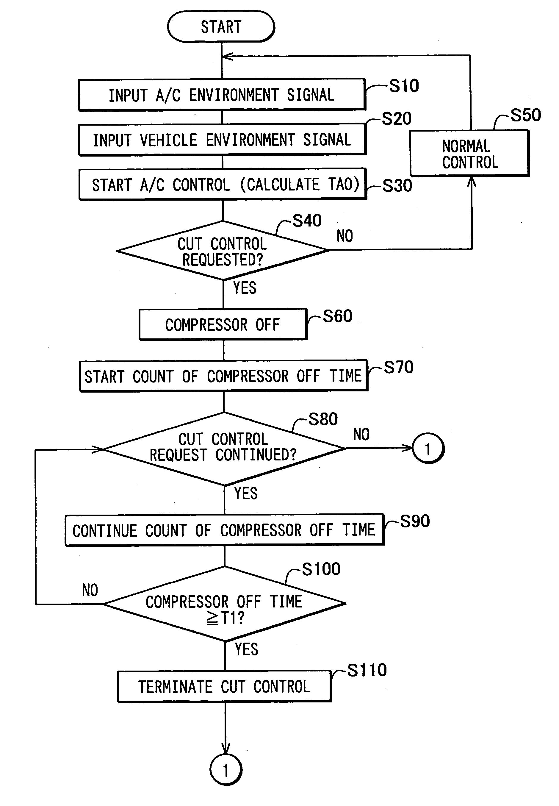
[0066] (Second Embodiment)

[0067] The second embodiment of the present invention will be now described with reference to FIG. 5.

[0068] In the above-described first embodiment, the electric compressor, which changes the work amount by changing the rotation speed, is used as the compressor 23. Further, the target rotation speed is corrected to be increased immediately after the cut control is terminated. To the contrary, in the second embodiment, a well-known variable displacement compressor is used as the compressor 23. The variable displacement compressor changes the work amount by changing a discharge amount per rotation. A target discharge amount is corrected to be increased more than a calculated discharge amount that is calculated based on the heat load, immediately after the cut control is terminated.

[0069] In the second embodiment, steps S130, S140 and S150 in FIG. 3B of the first embodiment are modified to steps S131, S141 and S151 in FIG. 5, respectively. As described in the ...

third embodiment

[0071] (Third Embodiment)

[0072] The third embodiment of the present invention will be now described with reference to FIG. 6.

[0073] In the above-described first embodiment, the electric compressor, in which the work amount is changed by changing the rotation speed, is used as the compressor 23. Further, the target rotation speed is corrected to be increased immediately after the cut control is terminated. To the contrary, in the third embodiment, a fixed displacement compressor, which includes an electromagnetic clutch, is used as the compressor 23. ON / OFF of the electromagnetic clutch is controlled so that the actual evaporator air temperature TE approximates to the target evaporator air temperature TEO. Then, in the cooling operation, the target evaporator air temperature TEO is corrected to be decreased immediately after the cut control is terminated.

[0074] In the third embodiment, steps S130, S140 and S150 in the first embodiment are modified to steps S132, S142 and S152 in FIG....


PUM


Abstract

In a normal control of a vehicle air conditioner, a control unit controls a compressor so that a work amount of the compressor is maintained at a target work amount calculated based on a heat load. In a cut control, the control unit controls the compressor so that the work amount is forcibly reduced smaller than the target work amount. When the cut control is set from the normal control, the cut control is continued for a predetermined time and then is changed to the normal control again. In this case, the work amount of the compressor immediately after the predetermined time passes is corrected to be increased. Thus, the target work amount of the compressor immediately after the cut control is increased larger than the target work amount calculated based on the heat load. Therefore, suitable air conditioning can be performed immediately after the cut control.

Description

[0001] This application is based on Japanese Patent Application No. 2003-44177 filed on Feb. 21, 2003, the disclosure of which is incorporated herein by reference.[0002] 1. Field of the Invention[0003] The present invention relates to an air conditioner for a vehicle. More particularly, the present invention relates to a control system for controlling a work amount (operation amount) of a compressor in the air conditioner.[0004] 2. Description of Related Art[0005] In a conventional vehicle, a cut control of a compressor is performed when the vehicle is accelerated in order to pass other vehicle which runs forward. The cut control of the compressor is a control for ensuring an acceleration of a vehicle engine by reducing a load of the compressor which is driven by the vehicle engine. For example, the cut control of the compressor in a vehicle acceleration is disclosed in U.S. Pat. No. 5,257,507 (corresponding to JP-A-H5-58151). Specifically, the cut control is performed when a runnin...

Claims


Application Information

Patent Timeline
IPC IPC(8): B60H1/22B60H1/32F25B49/02
CPCB60H1/3205B60H1/3211B60H1/3213B60H2001/3266B60H2001/327F25B2700/21173B60H2001/3275B60H2001/3292B60H2001/3294F25B49/022B60H2001/3272
Inventor NAKAMURA, HIROKITAKECHI, TETSUYA
Owner DENSO CORP
Why Eureka
Try Eureka