Pallet transfer system

a transfer system and pallet technology, applied in the field of pallet transfer system, can solve the problems of limited weight of work pieces placed on pallets, long extension distance of arms in stacker cranes, high cost, etc., and achieve the effects of reducing the size of the crane device, reducing the length of extension and retraction of arms in the back and front directions, and limiting the weight of work pieces

Inactive Publication Date: 2011-01-04
OKUMA CORP
View PDF4 Cites 5 Cited by
  • Summary
  • Abstract
  • Description
  • Claims
  • Application Information

AI Technical Summary

Benefits of technology

According to the present invention, an intermediate station is provided between a rail and a pallet stand-by position in order to temporally place a pallet. The pallet is transferred using the intermediate station as a pallet temporarily placing position. Therefore, a length of extension and retraction of the arms in the back and front directions can be shortened which reduces a crane device size. Further, it is not necessary to limit a weight of a work piece to be placed on a pallet. Thus, flexibility is improved and the pallet transfer system and can be applied to a pallet conveying device having a conventional crane device.
Further, at the intermediate station, a pair of lift arms and a lifting device at the intermediate station are provided. The pair of a lift arm supports the pallet at the pallet temporarily placing position and the lifting device raise and lowers the lift arm. At the pallet stand- by position, a conveying plate and transferring means are provided. The conveying plate can place the pallet thereon and the transferring means is to horizontally move the conveying plate to the pallet temporally placing position. In the pallet transfer system, the pallet on the conveying plate at the pallet stand-by position is carried to the pallet temporally placing position by horizontally moving of the conveying plate, and is transferred from the conveying plate to the intermediate station by the raised and lowered lift arms which support the pallet. Further, the crane device is moved toward the intermediate station side so as to enter into a space between the lift arms on a lower side of the pallet, and the pallet supported by the lift arms at the pallet temporally placing position is transferred to the crane device from the lift arms by relatively up and down moving between the crane device and the lift arms. Therefore, it is not necessary to provide a driving device to raise and lower a conveying plate on the pallet stand-by position side, and a structure of the tool on the pallet stand-by position side, that is, a structure of a machine tool can be simplified. When a heavy work piece is transferred, a pallet can be transferred more smoothly and stably than a system where the pallet is transferred by up and down moving of a conveying plate. Furthermore, a larger space for entering the crane device can be kept on the lower side of the because the transfer means for a conveying plate is provided on the machine tool side, the pallet is raised and supported by lift arms, and the conveying plate is retreated when the crane device is entered.
According to the second aspect of the present invention, the conveying plate includes a first positioning pin to determine a position of a pallet which is in a state placed on the plate. The crane device includes a second positioning pin to determine the position of a pallet which is in a state supported by the device. The pallet includes a pin hole capable of being inserted with both of the first positioning pin and the second positioning pin, and a pin hole for the first positioning pin and a pin hole for the second positioning pin are shared with this pin hole. Therefore, a structure for determining the position of the pallet can be simplified which results in that a pallet can be simplified and a cost can be reduced.
According to the third aspect of the present invention, in addition to the first aspect, the intermediate station is provided adjacent to the pallet stand-by position. A pair of supporting walls is projected between the lift arms and a plurality of cam followers is arranged in the frontward and backward directions on the opposite side of the supporting walls. The conveying plate which is moving from the pallet stand-by position to the pallet temporally placing position is supported by the come followers so as to be horizontally movable. Therefore, when a pallet is transferred from the pallet stand-by position to the pallet temporarily placing position, the weight of a work piece does not cause deformation of the conveying plate or breakdown of the transfer means. Thus, the pallet transfer system can properly handle a larger work piece.

Problems solved by technology

However, when a pallet is directly received and transferred between the stand-by position and the stacker crane as described above, the extending distance of arms in the stacker crane may be long.
Therefore, the weight of a work piece placed on a pallet is limited depending on strength of the arms.
Further, when the size of arms (that is, a stacker crane) is increased in order to improve the strength of the arms, such a crane cannot be applied to a conventional machine tool, and a larger installation space and operation space become necessary, which results in high cost.
However, when an intermediate station is provided, the device size is enlarged and the structure of the device becomes complicated.

Method used


Image

  • Pallet transfer system
  • Pallet transfer system
  • Pallet transfer system

Examples


Embodiment Construction

A pallet transfer system as one embodiment of the present invention will be described below referring to drawings.

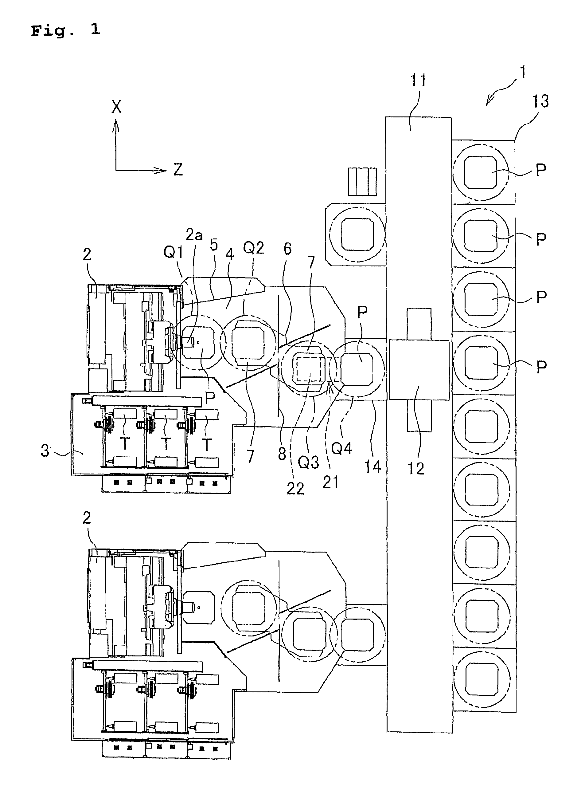
FIG. 1 is a view to illustrate the arrangements of a pallet conveying device 1 and horizontal machining centers 2, 2 from an upper direction. In addition, an X axis direction is a horizontal direction of a pallet transfer system, a Z axis direction is a front and back directions of the system, and a Y axis direction (inside and outside directions in FIG. 1) vertically crossing the X axis and the Z axis is a vertical direction of the system.

A horizontal machining center 2 is movable in the X axis direction and the Y axis direction which is a vertical direction, and includes a main spindle 2a as a rotary axis in the Z axis direction. The machining center main body adjacently includes a tool magazine 3 for housing tools on a left side thereof, the tools T, T . . . are to be attached to the main spindle 2a. Further, a machining space 4 for machining a work piece (not illustr...


PUM

PropertyMeasurementUnit
distanceaaaaaaaaaa
weightaaaaaaaaaa
strengthaaaaaaaaaa

Abstract

A pallet transfer system capable of smoothly transferring a pallet between a machine tool and a pallet conveying device is provided. The pallet transfer system includes an intermediated station to temporally place a pallet between a front ward position of a pallet stand-by position and the pallet stand by position. The pallet on a conveying plate at a stand-by position is carried to a temporary placing position by horizontally moving the conveying plate. Then the pallet is transferred to the intermediate position by being supported by lift arms which are raised from the conveying plate. Further, the pallet, supported by the lift arms, is transferred from the intermediate station to a stacker crane by advancing the stacker crane toward the intermediate station side and entered into an entering space below the pallet.

Description

This application claims the benefit of Japanese Patent Application Number 2007-117537 filed on Apr. 26, 2007, the entire contents of which are incorporated by reference.BACKGROUND OF THE INVENTION1. Field of the InventionThe present invention relates to a pallet transfer system for transferring a pallet, on which a work piece is placed, between a machine tool, e.g., a horizontal machining center, and a pallet conveying device having a stacker crane.2. Description of the Background ArtPatent document 1 discloses a conventional machine tool having a pallet exchanger where a pallet on which a work piece is placed is exchanged between a machining-side position and a stand-by position by rotation of the pallet. In the conventional machine tool as disclosed in Patent document 1, a stacker crane is used when a pallet is exchanged and carried between the stand-by position of the machine tool and a pallet housing station which is separately provided from the machine tool. The stacker crane i...

Claims


Application Information

Patent Timeline
Patent Type & Authority Patents(United States)
IPC IPC(8): B65G65/00
CPCB23Q7/1431B65G1/0407Y10T29/5196
Inventor KIRIYAMA, MASAYUKI
Owner OKUMA CORP
Why Eureka
Try Eureka