
Method for improving capacity of a reverse link channel in a wireless network

a reverse link channel and wireless network technology, applied in the field of wireless communication networks, can solve the problems of deteriorating the quality of the received pilot channel signal, the interference of the pilot channel of each of the users, and the interference of the received signals

Active Publication Date: 2004-09-09
ALCATEL-LUCENT USA INC
View PDF4 Cites 27 Cited by
  • Summary
  • Abstract
  • Description
  • Claims
  • Application Information

AI Technical Summary

Problems solved by technology

The higher the received power in a signal, the better the decoding ability of that signal at the base station but on the other hand, if the received power from one user is high, it leads to a higher interference to another user who is also transmitting at the same time.
If the transmission was not successful, then the base station may or may not discard the received signal.
When the assigned data users start transmitting, the pilot channel of each of them is interfered with by the received signals of the other data users.
This leads to a deterioration of the received pilot channel signal quality, prompting the power control mechanism to order the mobile users to increase their pilot channel transmit powers.
Additionally, aside from the anticipated increase in interference due to the assigned data users' bursts, the current received value of the pilot signal power itself may be low and unsatisfactory in comparison with a certain desired value due to the rapidly changing nature of the radio link between MS and BS.
The rate of change of the pilot transmit powers (and hence of the improvement in received pilot channel signal quality) afforded by power control is slow and hence unable to track either the surge in interference or a deep fade in the channel if there is one.
Hence, in situations where the assigned transmission time interval is relatively short, the improvement of the pilot channel signal quality during the duration of the transmission due to power control may not be sufficient for satisfactory channel estimation.
More generally, when the expected receive power in the pilot channel is lower than a pre-defined threshold; the base station will not be able to estimate the channel properly.
This erroneous channel estimation would result in a failure of the received data decoding.

Method used


Image

  • Method for improving capacity of a reverse link channel in a wireless network
  • Method for improving capacity of a reverse link channel in a wireless network
  • Method for improving capacity of a reverse link channel in a wireless network

Examples


Embodiment Construction

FOR PCTP AND DCPR ARE

[0034] Pilot boost / de-boost is picked from a pre-defined set of eight values as shown {-3, 0, 3, 5, 6, 7, 8, 9} dB. This arrangement requires a bit field length of 3 bits.

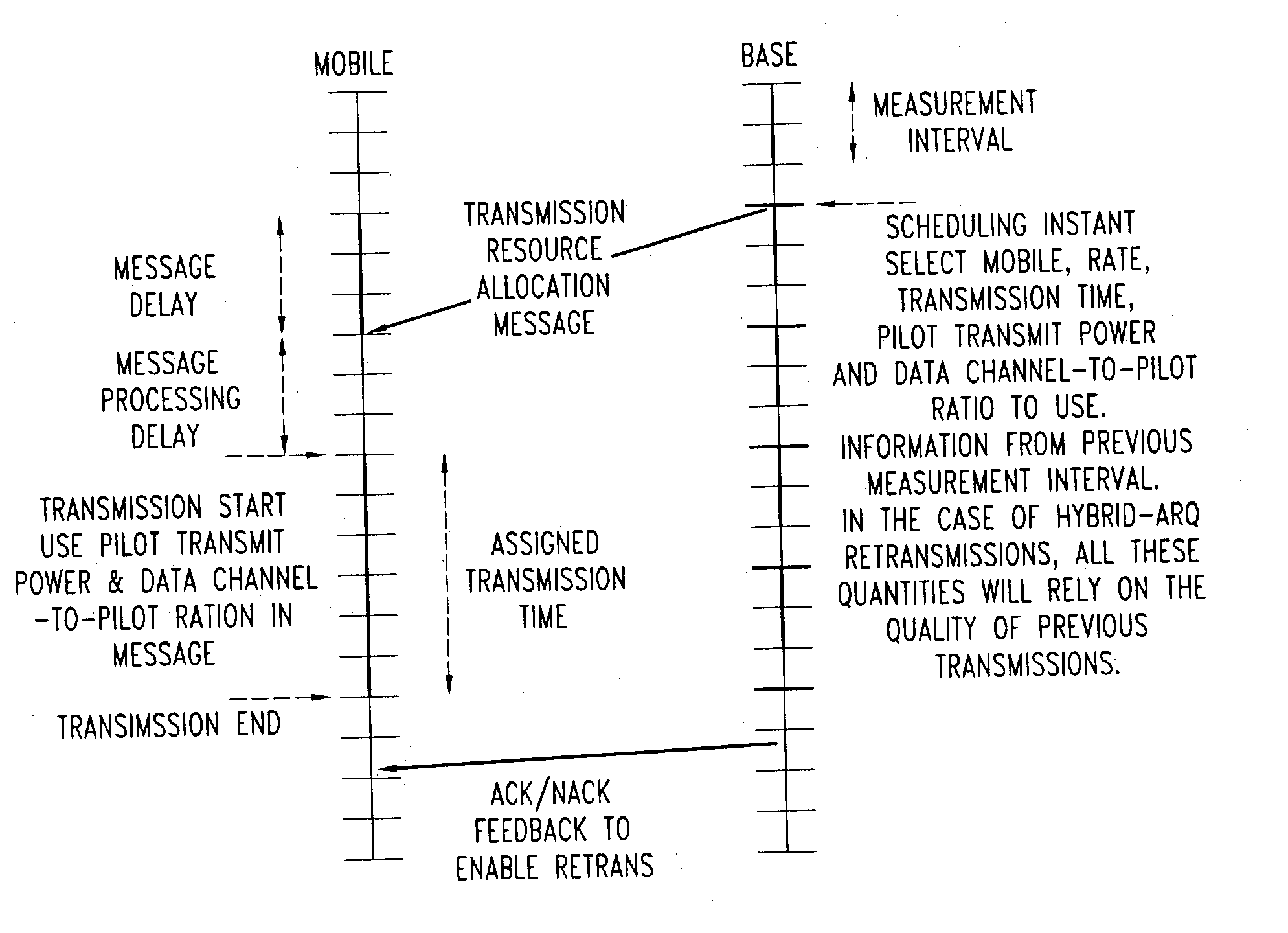
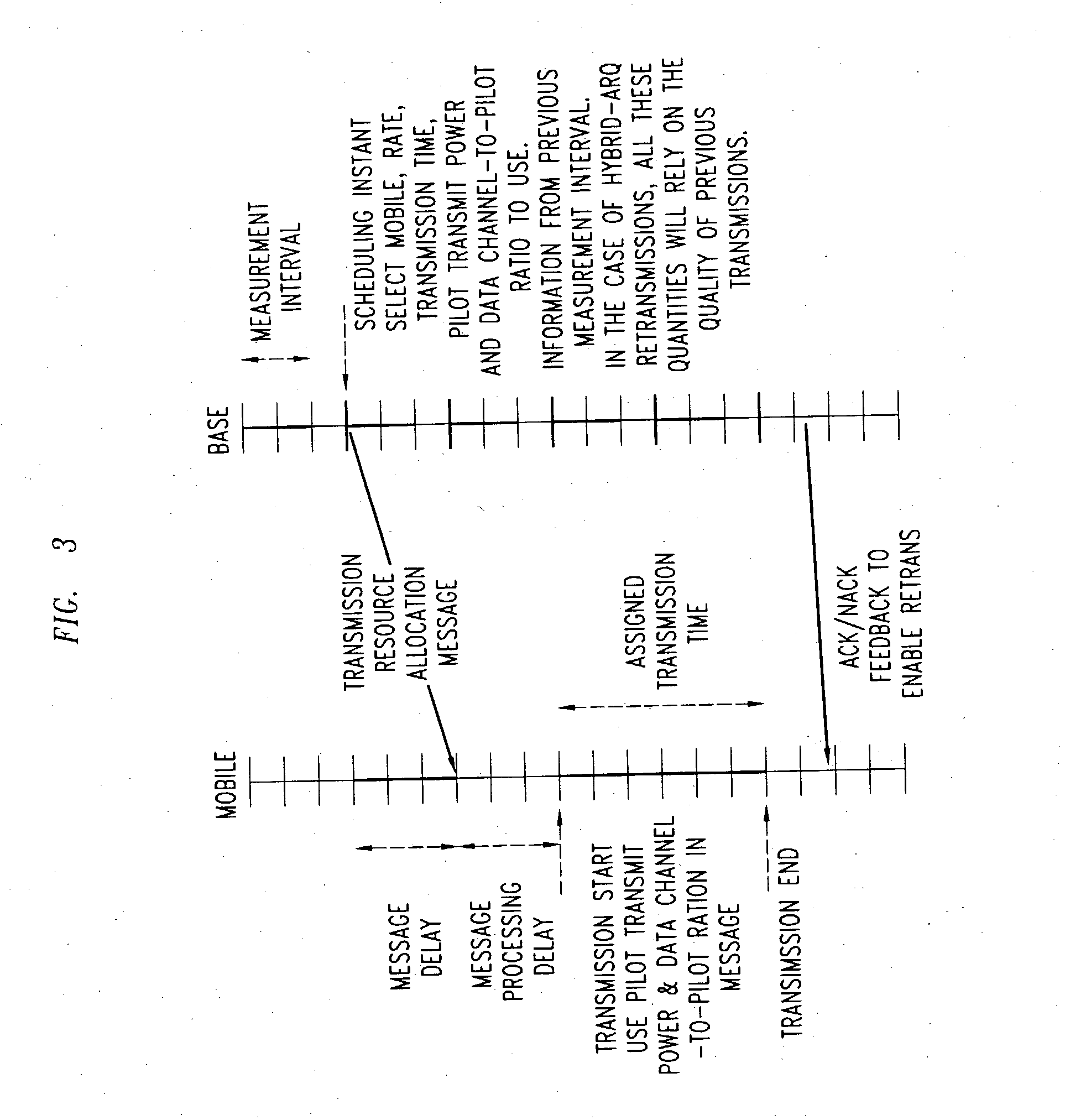
[0035] DCPR is picked from a pre-defined set of 16 values as shown [-15, 0] in the steps of 1 dB. The above arrangement requires a bit field length of 4 bits. The base station conveys the scheduling decision(s) to the scheduled user(s). For the data users scheduled for a transmission, the resource assignment includes the pilot transmit power or an adjustment factor to the current pilot transmit power to use at the start of the transmission, and the data channel-to-pilot ratio (or the offset from the default value of the appropriate data channel-to-pilot ratio) to use during transmission. After certain propagation and processing delay, the assigned data users start their transmissions. At the start of the transmission, the user transmits the pilot channel at the power level (or adjustment) indic...


PUM


Abstract

An embodiment of the present invention provides a method for improving the capacity of a reverse link by realizing a scheme to effect sharp changes in pilot channel transmit power (PCTP) and data channel to pilot power ratio (DCPR), coordinated with the start of the data channel transmission. The change in pilot power and data channel to pilot power ratio is also applicable to mobiles that use multiple pilots and / or multiple antennas at the transmitter and / or receiver.

Description

[0001] 1. Field of the Invention[0002] The invention relates to a wireless communications network and more particularly to improve the capacity of a reverse link of a communication channel.[0003] 2. Background of the Invention[0004] In a wireless network the communication is described in terms of Forward Link (FL) and Reverse Link (RL). The Forward Link and Reverse Links are also referred to as Down Link (DL) and Up Link (UL) respectively. The forward link refers to the transmission from the Base Station (BS) also referred to as Cell to a Mobile Station (MS) and the reverse link refers to the transmission from the MS to a BS. A Mobile Station could be a voice terminal or a data terminal or a combination thereof. Both forward and reverse links transfer or carry content of voice, data, video or any other digital information from one end to the other end. The information transmitted from a Base Station to a specific Mobile Station is uniquely identified in nature compared to the inform...

Claims


Application Information

Patent Timeline
IPC IPC(8): H04B7/005H04L29/00H04B7/26H04L1/18H04W52/16H04W52/32H04W52/50
CPCH04L1/1812H04W52/50H04W52/32H04W52/16B63B35/38F16L21/06
Inventor GOPALAKRISHNAN, NANDURAMAKRISHNA, SUDHIRSUNDARAM, GANAPATHY SUBRAMANIAN
Owner ALCATEL-LUCENT USA INC
Learn More