All-optical flip-flop

a flip-flop, all-optical technology, applied in the field of flip-flops, can solve the problem of not being able to achieve the remaining oscillation mod

Inactive Publication Date: 2004-09-30
JAPAN SCI & TECH CORP
View PDF4 Cites 7 Cited by
  • Summary
  • Abstract
  • Description
  • Claims
  • Application Information

AI Technical Summary

Problems solved by technology

In this state, the gain of the laser is consumed only by this set mode, which means that while one of two m

Method used

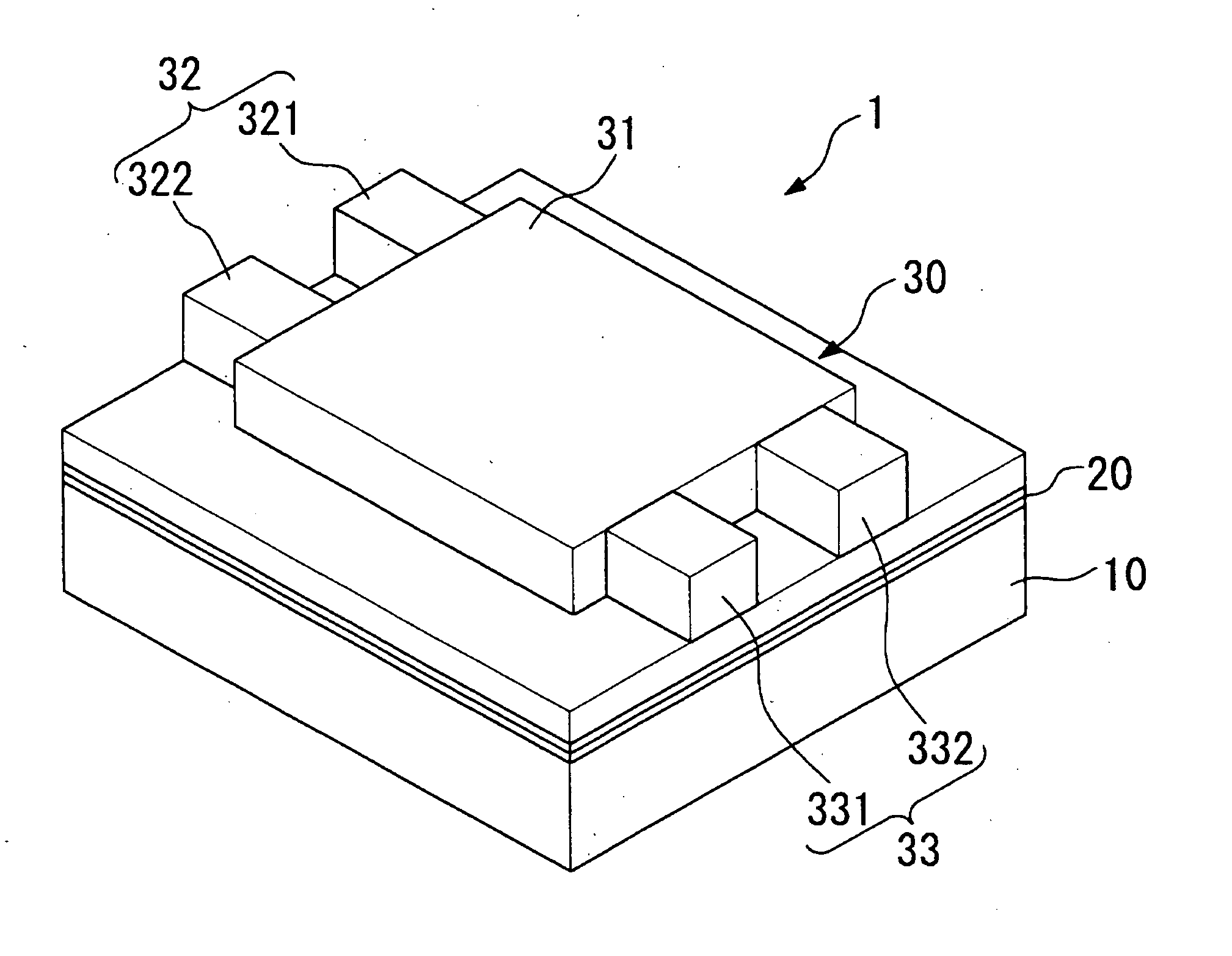
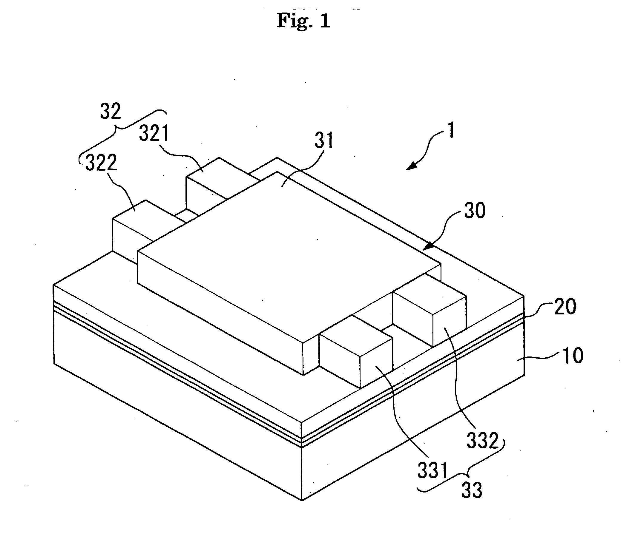
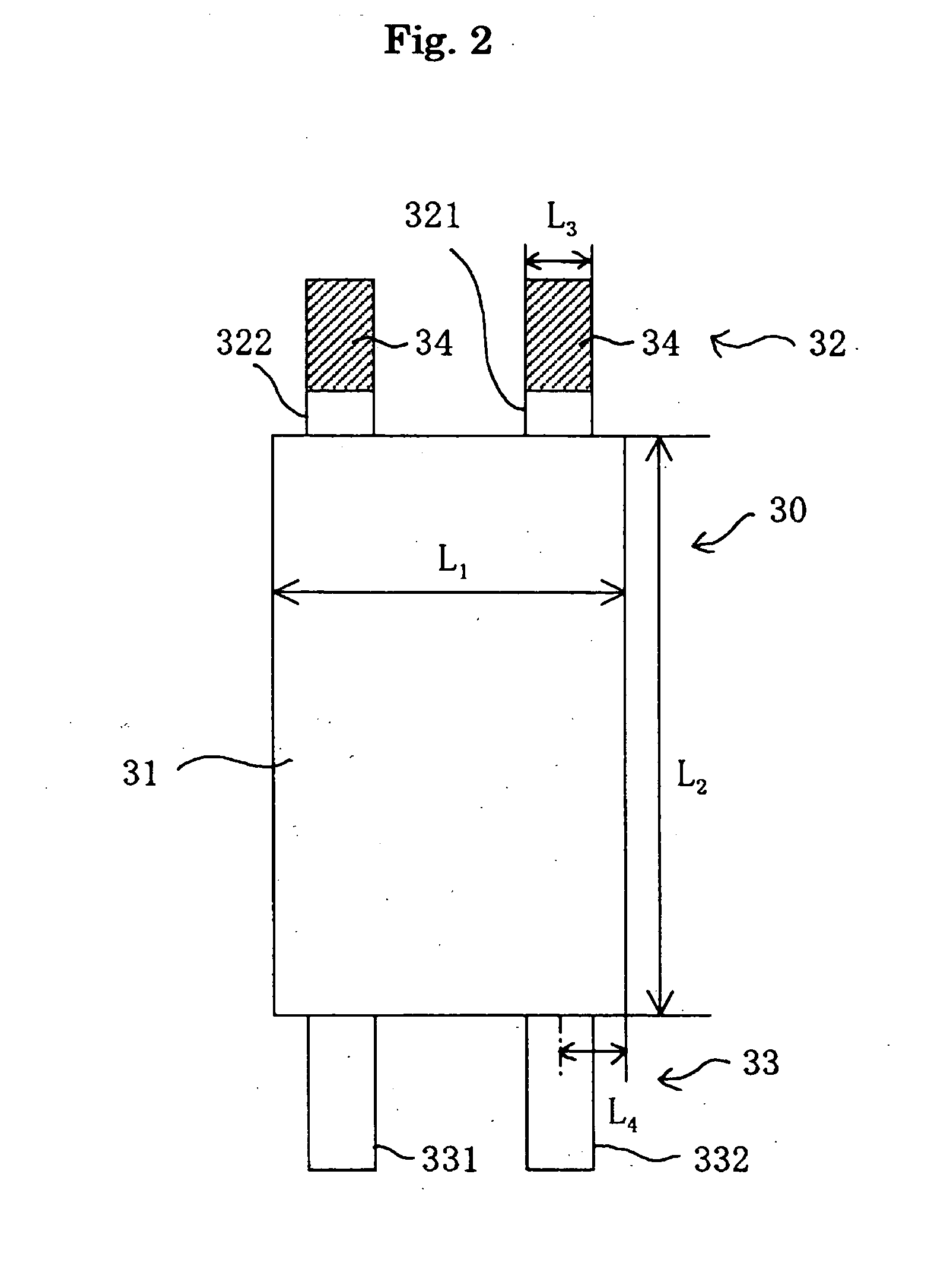

Image

  • All-optical flip-flop
  • All-optical flip-flop
  • All-optical flip-flop

Examples


Embodiment Construction

)

[0060] An experimental examples is described in the following based on the structure of the first embodiment.

[0061] Experimental conditions: Same as for the examples given in the first embodiment. However, the length of the multimode interference portion 31 is taken to be 595 .mu.m.

[0062] A current--light output characteristic of this experimental example is shown in FIG. 7.

[0063] In FIG. 7, hysterisis appears at an oscillation threshold value. In the present invention, the multimode interference portion 31 constituting a multimode waveguide is incorporated as part of an oscillator, and it is possible to obtain a clear hysterisis loop using absorption saturation. The reason for this is that the multi-mode interference portion incorporated in the oscillator acts as a countermeasure with regards to manufacturing differences and provides superior stability.

[0064] As can be understood from this characteristic, according to the invention of this application, it is possible to define a s...


PUM


Abstract

The present invention provides a set-reset flip-flop operating in an all-optical manner. In this invention, a set pulse is inputted from the setting port. In doing so, only oscillation in set mode is generated at the multi-mode interference portion in a waveguide. As a result, a non-inverting output Q is obtained from the non-inverting output port. This state is then continued even if the set pulse input goes off. Next, a reset pulse is inputted to the resetting port. In doing so, at the multi-mode interference portion, oscillation of light in the set mode is halted, and oscillation in the reset mode occurs. As a result, it is possible to obtain an inverting output Q-bar from the inverting output port. This state is then continued even if the reset pulse goes off.

Description

[0001] 1. Field of the Invention[0002] The present invention relates to a flip-flop that operates in an all-optical manner.[0003] 2. Description of the Related Art[0004] With the advancement of optical communication networks, an aim has been set to achieve all-optical signal processing. It is considered that, if this is achieved, this will bring about optical communication at a higher-speed with lower power consumption. Flip-flops that operate in an all-optical manner are therefore necessary as basic devices for enabling all-optical signal processing.[0005] It is therefore an object of the present invention to provide, in response to the aforementioned circumstances, a set-reset flip-flop capable of operating in an all-optical manner.[0006] An all-optical flip-flop of this invention is provided with a semiconductor laser. The semiconductor laser is equipped with a waveguide. The waveguide comprises a multimode interference portion, input port, and output port. The input port and out...

Claims


Application Information

Patent Timeline
IPC IPC(8): G02F1/01G02F3/00G02F3/02H01S3/082H01S5/50
CPCG02F1/0126G02F3/00G02F2201/05G02F2001/217G02F3/026G02F1/217
Inventor NAKANO, YOSHIAKITAKENAKA, MITSURU
Owner JAPAN SCI & TECH CORP
Why Eureka
Try Eureka