Cooling plate and manufacturing method thereof, and sputtering target and manufacturing method thereof thereof

a technology of cooling plate and manufacturing method, which is applied in the direction of manufacturing tools, lighting and heating apparatus, instruments, etc., can solve the problems of further productivity and cost, unsatisfactory quality and accuracy, and inability to achieve direct cooling

Inactive Publication Date: 2004-10-07
HITACHI LTD +1
View PDF3 Cites 25 Cited by
  • Summary
  • Abstract
  • Description
  • Claims
  • Application Information

AI Technical Summary

Benefits of technology

[0016] By using the friction stir welding method, since it is possible to perform joining at a low temperature below the fusing point of a joining material, distortion by the joining is small in comparison with a conventional welding method, and hence a cooling plate with high accuracy can be manufactured. Hence, it is possible to simplify the correction step after joining, and to reduce cost by shortening correction work-hours.
[0039] Thus, it becomes possible to manufacture a backing plate, which has small heat distortion after joining and has good quality, by producing the backing plate for sputtering as a cooling plate with using friction stir welding.

Problems solved by technology

However, since it is necessary to make a surface flat by correction or machining after joining because these welding methods have large heat distortion after joining, they have problems in respect of quality, and accuracy, and further productivity and cost.
Furthermore, in the above-described known example, although the structure that a target is provided through a plate-like base section provided on a plate-like cooling section which has a coolant passage is shown, not only direct cooling cannot be obtained, but also the formation of a compact cooling passage cannot be obtained.
That is, since a plastic flow phenomenon by the frictional heat between the rotation tool and joined material is used, this is different from conventional welding such as electric arc welding and electron beam welding, but does not perform joining (welding) with melting the joined material.
When the rotation tool rotates counterclockwise, a minute defect may arise in the right-hand side to the traveling direction of the rotation tool rarely.
However, when the channel is located in the left-hand side, a defect will arise inside the body and will not arise near the channel.
If the rotation tool is on the lid above the channel, copper etc. will be deformed and collapsed due to this load, and a part of a wall will escape into the channel so that the joining will not be successful.
As described above, when the rotation tool rotates counterclockwise, a defect may arise in the right-hand side to the traveling direction of the rotation tool rarely.
Moreover, in the friction stir welding, since the rotation tool that is rotating forcibly moves against a workpiece, so to speak, the workpiece receives a large force from the rotation tool.
However, it is comparatively difficult to fix the lid because the channel winds and has the complicated geometry.
Unlike permanent joining, temporary attachment has narrow joining sections and heat input is not large, and hence, a conventional welding method is also sufficient.
This is because cost increase due to a plurality of processes.
What becomes a problem here is that a resistance force generated when inserting or moving the rotation tool to the joining is about 10 kN or more.
However, it is comparatively difficult to fix the lid because the channel winds and has the complicated geometry.
Unlike permanent joining, temporary attachment has narrow joining sections and heat input is not large, and hence, a conventional welding method is also sufficient.
This is because cost increase due to a plurality of processes.
Since the rotation tool is forcibly inserted in the joining at the starting point, a resistance force that the rotation tool receives is large, and the heat input also becomes large.
Incidentally, in the case of aluminum, since a fusing point is low and strength is also low, the temperature is sufficient at only about 450.degree. C.
At the time of manufacturing a copper backing plate by the friction stir welding, several troubles arise since joining temperature becomes high as described above.
These are troubles caused by the material being copper.
First, what is an issue is that a motor and a spindle that rotate a rotation tool also become hot due to heat transfer since the temperature of the rotation tool itself also becomes hot because of high joining temperature.
Although there is also exhaustion of the rotation tool itself, exhaustion of an apparatus is rather an issue.
In order to perform joining completely, it is not possible to decrease the temperature of the joining.
In addition, in the case of a large backing plate, joining length becomes long and a heating value also becomes large.

Method used


Image

  • Cooling plate and manufacturing method thereof, and sputtering target and manufacturing method thereof thereof
  • Cooling plate and manufacturing method thereof, and sputtering target and manufacturing method thereof thereof
  • Cooling plate and manufacturing method thereof, and sputtering target and manufacturing method thereof thereof

Examples


embodiment 1

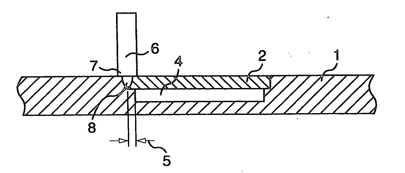
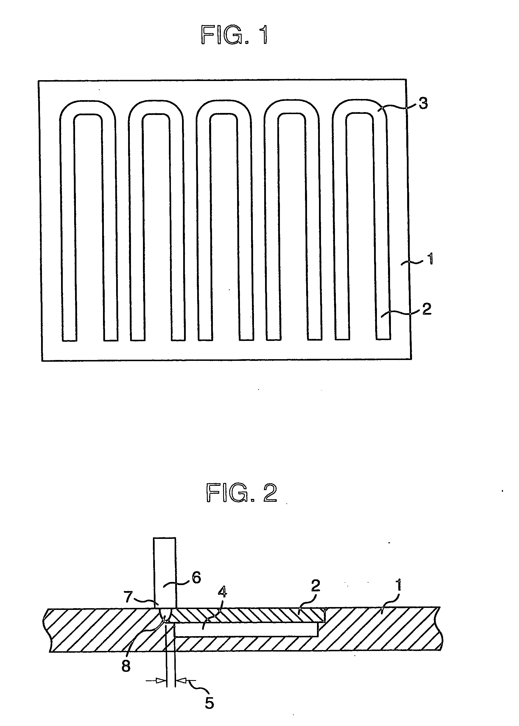
[0056] FIG. 1 is a schematic front view of a backing plate as a cooling plate made of oxygen free copper or a copper alloy containing 5% or less of Zr or Cr. The backing plate consists of a body 1 and a lid 2. A U-channel 4 is provided in the body 1, the lid 2 covers the channel 4, and, the lid 2 and channel 4 have the same plane and zigzag geometry although the lid 2 and channel 4 differ from each other in dimensions of U-shapes. Otherwise, I-shaped and S-shaped channels or the like are preferable. In addition, an R section 3 is provided in each corner section of the lid 2 in order to make the lid 2 easily inserted in the body 1. The lid 2 has the structure of being received with a step of the body 1, and can receive the force of the rotation tool 6 on the occasion of the friction stir welding.

[0057] The dimensions of the body 1 are 1500 L.times.1200 W.times.15 D mm. In he case of this FIG. 1, there are five channels 4 for cooling. If he dimensions are 1300 L.times.900 W.times.15 D...

embodiment 2

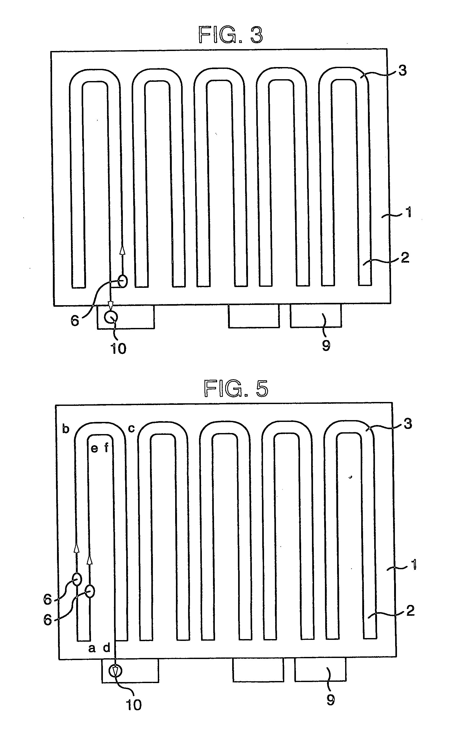
[0065] This embodiment relates to the joining of the backing plate similar to that in FIG. 1, and in particular, a joining example about the R section 3 will be described. The rotation speed of a rotation tool, joining speed, and rotation tool geometry are the same as those in the first embodiment. As shown in FIG. 5, after first inserting the rotation tool 6 in a position "a", joining was performed in the path of a.fwdarw.b.fwdarw.c.fwdarw.d under the above-described conditions, and the end section 10 was made to be the dummy 9. Next, after inserting the rotation tool 6 in a position "a" again, joining was performed in the path of a.fwdarw.e.fwdarw.f.fwdarw.d, and the end section 10 was similarly treated. What is important at this time is that the rotation tool 6 always turns to the right in the R section 3. When the rotary direction of the rotation tool is clockwise contrary to this, what is necessary is just to perform joining so that the rotation tool may always turn to the left...

embodiment 3

[0067] What are examined in this embodiment are the overlapping width 5 shown in FIG. 2, and the distance (offset) apart from a joining beveling of the centerline of the rotation tool 6 in a direction opposite to the channel 4. The geometry of the rotation tool that is used is the same as that in the first and second embodiments. In addition, joining conditions are the same.

2TABLE 2 Overlapping Maximum radius width Offset of pin State of w (mm) x (mm) W + x (mm) r (mm) joining 2.5 0 2.5 4.0 Collapse 2.5 1 3.5 4.0 Collapse 2.5 1.5 4.0 4.0 Good 1 0 1.0 4.0 Collapse 2 0 2.0 4.0 Collapse 3 0 3.0 4.0 Collapse 4 0 4.0 4.0 Good

[0068] As shown in Table 2, in order to obtain normal joining, it is preferable that w+x.gtoreq.r. That is, it is required for that the weld bead that is formed is in the outside of the channel. Moreover, a reason why the sample was not successful in joining is that the lid was collapsed due to the load received from the rotation tool.


PUM

PropertyMeasurementUnit
thicknessaaaaaaaaaa
resistance forceaaaaaaaaaa
areaaaaaaaaaaa

Abstract

The present invention is a cooling plate including a groove, which becomes a passage of a coolant, inside a body, wherein one or more fins are provided inside the groove, wherein the groove is covered with a lid having width larger than the groove, wherein the lid is joined to the body by friction stir welding, and wherein a weld bead formed by the joining is outside the passage, and the weld bead formed by the joining is formed within the body and further, is characterized by a manufacturing method of a cooling plate that has a first groove, which becomes a passage of a coolant, and a second groove, which has width larger than the first groove and receives a lid on the first groove, inside a body, receives the lid on the second groove, and is joined to the body, the manufacturing method of a cooling plate wherein, while the lid and the body are joined together by the friction stir welding owing to insertion of a rotation tool having a shoulder and a pin, the joining is performed so that a weld bead formed by the joining may become out of the passage, and furthermore, is characterized in that a target for sputtering is joined to the cooling plate.

Description

[0001] The present invention relates to a new cooling plate and a manufacturing method thereof, a sputtering target and a manufacturing method thereof, a backing plate and a manufacturing method thereof, and a sputtering target and a manufacturing method thereof.PRIOR ART[0002] Although a cooling plate is widely used industrially, an efficient cooling function is required. For example, in a sputtering apparatus, efficient radiation of the heat generated in a target material affects the performance of a thin film that is obtained. In particular, in the case of a sputtering apparatus for a liquid crystal manufacturing apparatus, a target material with a large area is used, which radiates plenty of heat. For this reason, a backing plate is used as a cooling plate, the backing plate having a channel inside a smooth plate composed of copper, a copper alloy, aluminum, or an aluminum alloy, and having the structure that the channel is covered with a lid and the lid and cooling plate are me...

Claims


Application Information

Patent Timeline
Patent Type & Authority Applications(United States)
IPC IPC(8): G02F1/1343B23K20/12B23K101/14B23P15/26C23C14/34F28F3/12
CPCB23K20/122B23K20/1235B23P15/26C23C14/3407F28F3/12Y10T29/49353H01J37/3497Y10T29/49393Y10T29/4935Y10T29/49391H01J37/34C23C14/34
Inventor OKAMOTO, KAZUTAKADOI, MASAYUKIOKAMURA, HISANORIAONO, YASUHISAKAGAWA, MANABUHIRANO, SATOSHIAOTA, KINYA
Owner HITACHI LTD
Why Eureka
Try Eureka