
Device for bracing a shell in an aircraft fuselage

a technology for aircraft fuselage and shell, which is applied in the direction of fuselage, fuselage bulkheads, aircraft accessories, etc., can solve the problems of expensive stringers whose geometry and stringers cannot be produced to achieve the desired shap

Inactive Publication Date: 2004-10-07
SAAB AB
View PDF8 Cites 13 Cited by
  • Summary
  • Abstract
  • Description
  • Claims
  • Application Information

AI Technical Summary

Benefits of technology

[0016] When the stringer according to the invention is being mounted against the shell surface, it can be easily bent and conformed to the shape of the shell surface. After mounting, the stringer and the shell surface together form a strong and rigid unit.
[0017] One advantage of the solution according to the invention is that both the stringer and the shell surface are soft and workable prior to their being assembled together, while the finished assembled structure is strong and stable. The workable stringer radically affects durability and strength vis-a-vis loads that are perpendicular to a sheet surface, while the costs of conforming the stringer can at the same time be kept at a very low level.

Problems solved by technology

One problem with using stringers is that it is very expensive to produce stringers whose geometry conforms to the location in the aircraft where the element is to be used.
When the surface of the fuselage is curved it is necessary to either mill or stretch the stringer into the desired shape, which is very expensive.

Method used


Image

  • Device for bracing a shell in an aircraft fuselage
  • Device for bracing a shell in an aircraft fuselage
  • Device for bracing a shell in an aircraft fuselage

Examples


Embodiment Construction

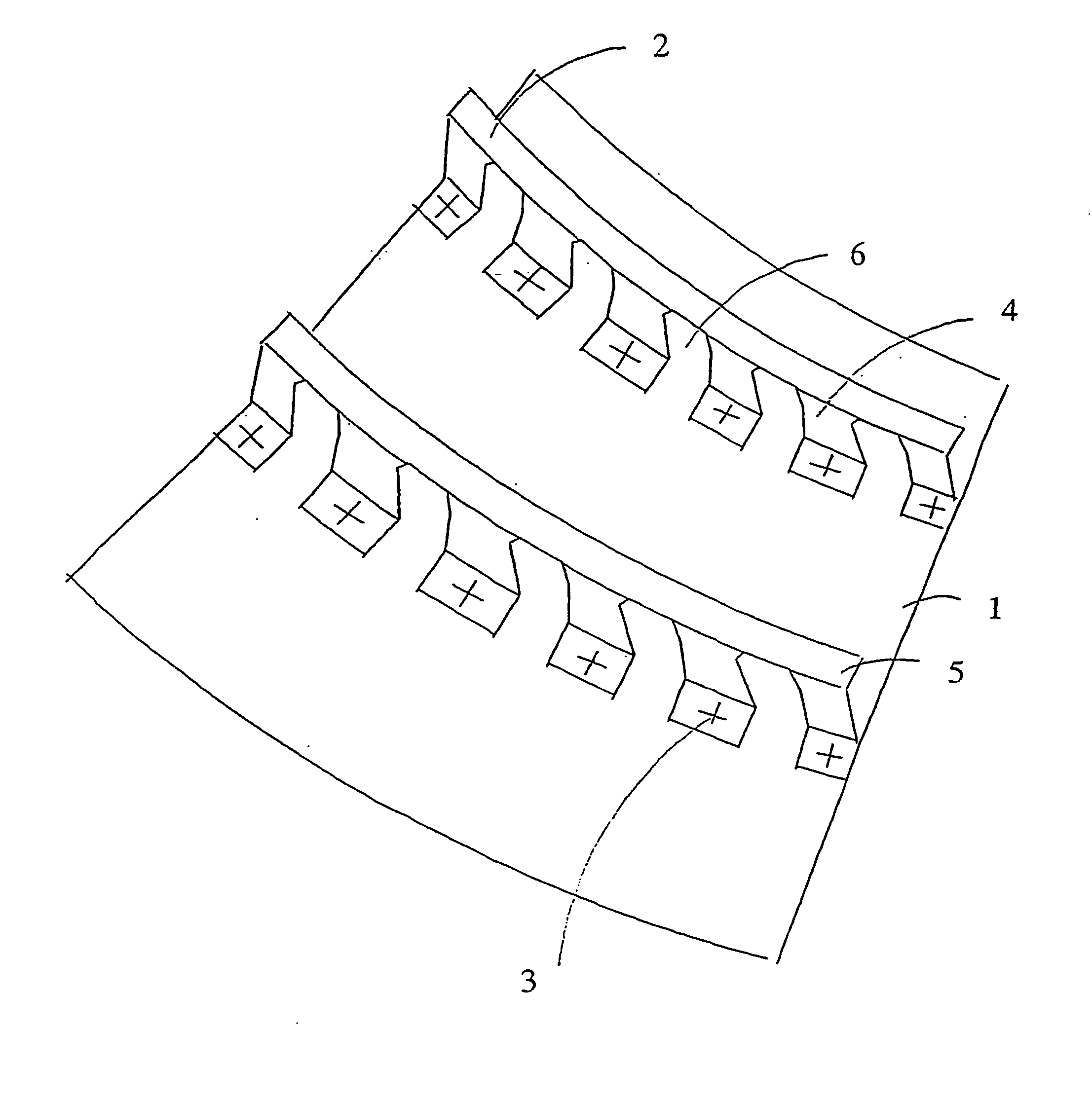
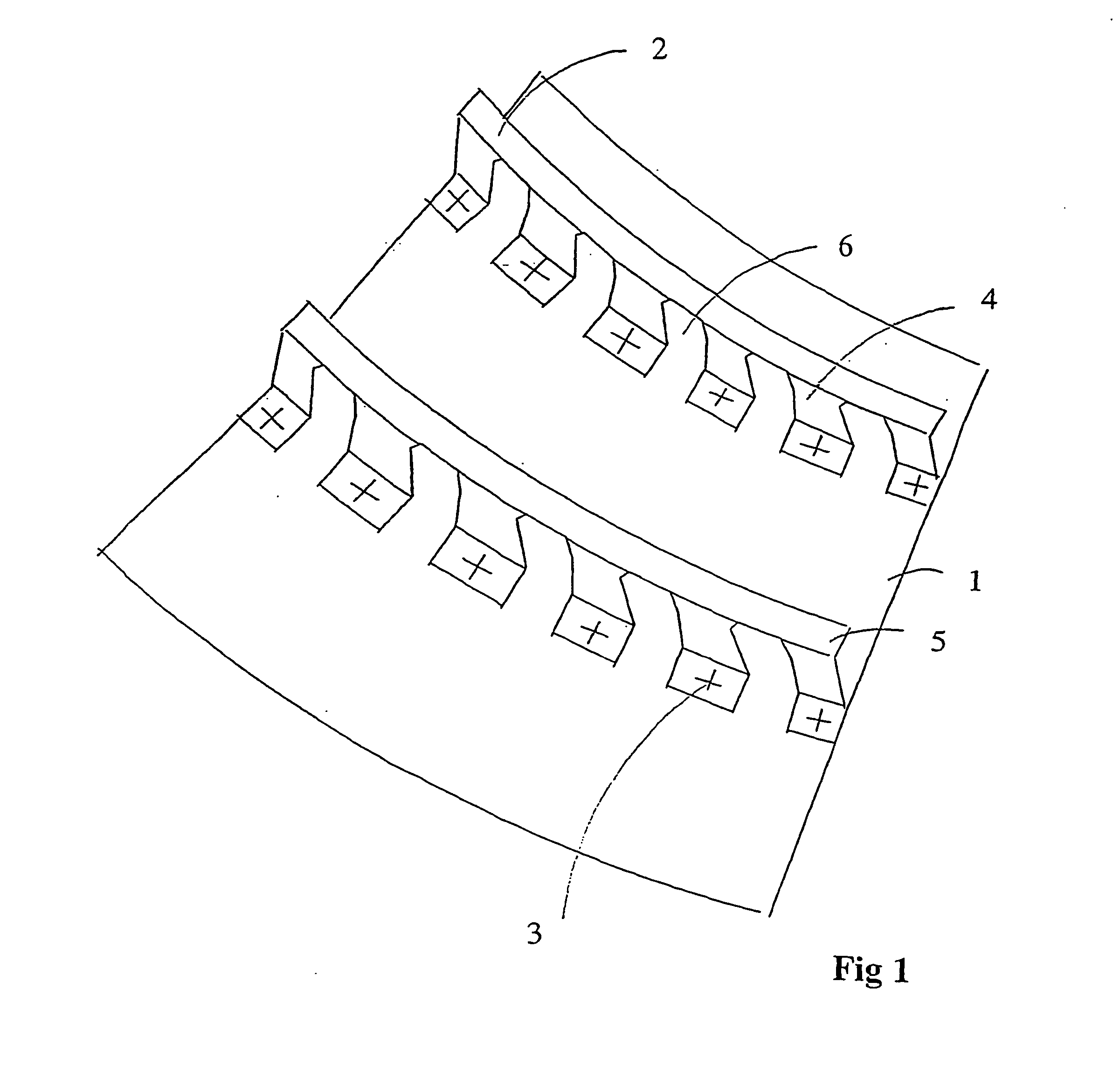
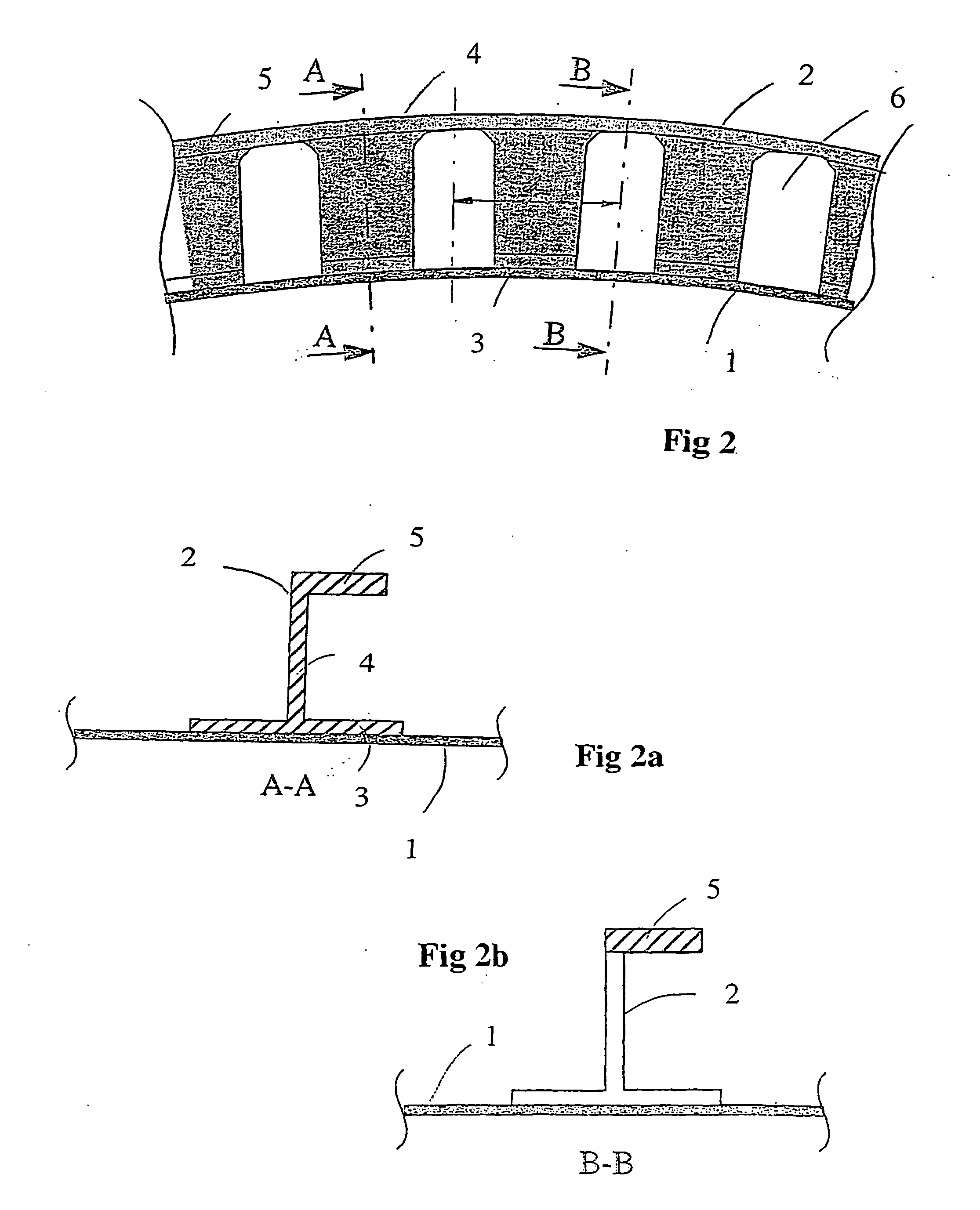
[0015] The foregoing problem is described by means of a new stringer design. In the design according to the invention a continuous profile of, e.g. light metal is used as a stringer. Notches are made at a regular distance apart from each other in at least a portion of the profile. The notches extend through a base surface in the profile and through an intermediate part in the direction perpendicular to the base surface. The profile also contains an upper surface that is parallel to said base surface, which upper surface is not encompassed by said notches.

[0016] When the stringer according to the invention is being mounted against the shell surface, it can be easily bent and conformed to the shape of the shell surface. After mounting, the stringer and the shell surface together form a strong and rigid unit.

[0017] One advantage of the solution according to the invention is that both the stringer and the shell surface are soft and workable prior to their being assembled together, while...


PUM


Abstract

A device for bracing a shell surface (1) in an aircraft fuselage against deformations and consisting of a continuous profile that is arranged so as, after conformation, to be mounted against the shell surfaces. Notches (6) are spaced at regular distances apart from each other in at least a portion of the profile. The notches (6) extend through a base surface (3) in the profile, and through an intermediate part (4) perpendicular to the base surface (3). The notches (6) are delimited upwardly by an upper surface (5) that is not encompassed by said notches (6).

Description

TECHNICAL AREA[0001] This invention concerns a device for bracing a shell surface in an aircraft fuselage against deformations and consisting of a continuous profile that is arranged so as, after conformation, to be mounted against the shell surface.STATE OF THE ART[0002] All types of aircraft are subject to heavy stresses. Nevertheless, production methods must be simple in order to keep costs at acceptable levels. These somewhat contradictory criteria are particularly applicable in connection with the fabrication of curved surface sections or panel surfaces used for the fuselage, wings or other parts of the aircraft.[0003] Practically all outer surfaces of modern aircraft, be they military or civilian, are braced by means of one or more of the following methods:[0004] Frame ribs[0005] Stringers[0006] Cell layers (honeycomb sandwich)[0007] A stringer is often used in thin-sheet structures to brace a shell surface against deformations perpendicular to the sheet surface. Panels or out...

Claims


Application Information

Patent Timeline
IPC IPC(8): B64C1/12
CPCB64C1/12
Inventor BROFELDT, PAR
Owner SAAB AB
Learn More