Sealed coaxial cable connector and related method

a coaxial cable and connector technology, applied in the direction of couplings/cases, coupling device connections, securing/insulating coupling contact members, etc., can solve the problems of reducing signal strength, affecting performance, and infiltration of moisture into the interior of the connector and into the cabl

Inactive Publication Date: 2004-10-21
PPC BROADBAND INC
View PDF55 Cites 150 Cited by
  • Summary
  • Abstract
  • Description
  • Claims
  • Application Information

AI Technical Summary

Benefits of technology

0075] In a preferred modification to the sixth aspect, the body member further comprises an annular shoulder integrally connecting the proximal body section and the distal body section to one another, and the (c) inserting comprises situating the collar between the lip and the annular shoulder. The lip may optionally have a forward chamfer for facilitating insertion of the lip through the annular collar. The lip and th...

Problems solved by technology

A problem with prior coaxial cable designs, particularly in outdoor applications, has involved unwanted infiltration of moisture at the connector and into the interior of the cable.
This can impair performance, for example, by leading to corrosion, affecting the electrical characteristics within the cable, increasing contact resistance, reducing signal strength, causing excessive RF leakage from the connector, etc.
During assembly, the compression sleeve can easily become lost because of its typically small size and bec...

Method used


Image

  • Sealed coaxial cable connector and related method
  • Sealed coaxial cable connector and related method
  • Sealed coaxial cable connector and related method

Examples


Embodiment Construction

[0103] Reference will now be made in detail to the presently preferred embodiments and methods of the invention as illustrated in the accompanying drawings, in which like reference characters designate like or corresponding parts throughout the drawings. It should be noted, however, that the invention in its broader aspects is not limited to the specific details, representative devices and methods, and illustrative examples shown and described in this section in connection with the preferred embodiments and methods. The invention according to its various aspects is particularly pointed out and distinctly claimed in the attached claims read in view of this specification, and appropriate equivalents.

[0104] It is to be noted that, as used in the specification and the appended claims, the singular forms "a," "an," and "the" may include plural referents unless the context clearly dictates otherwise.

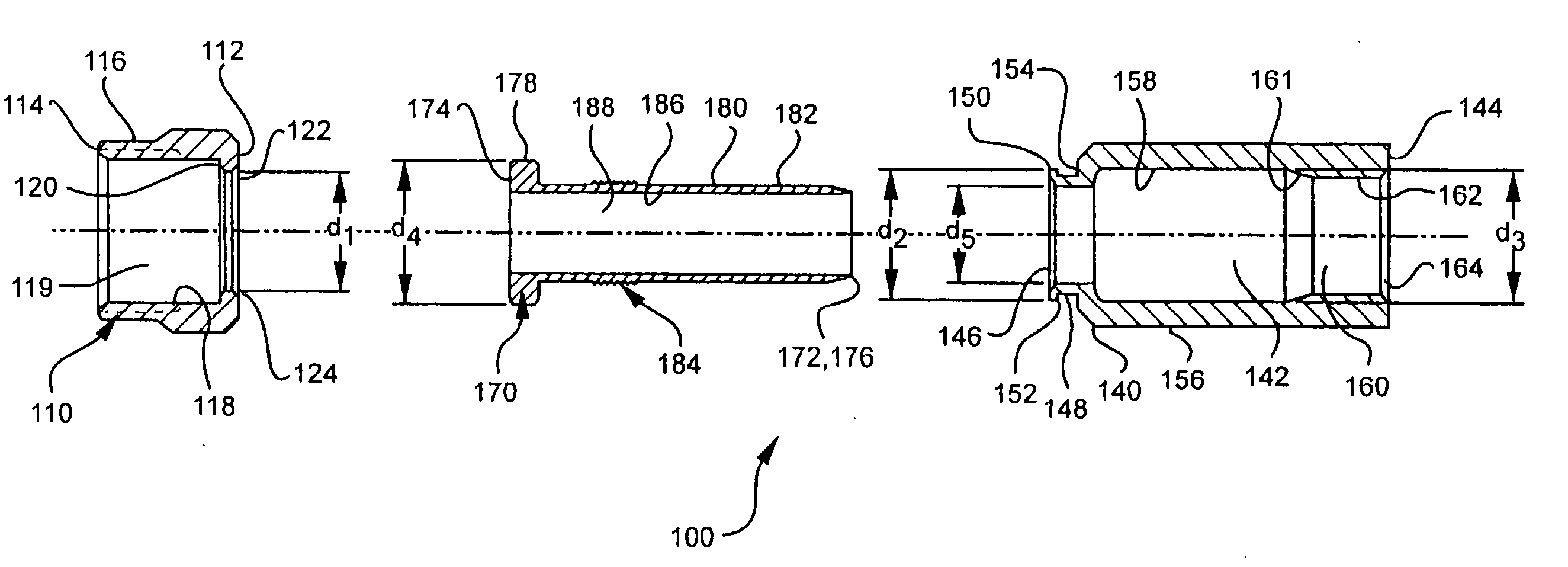
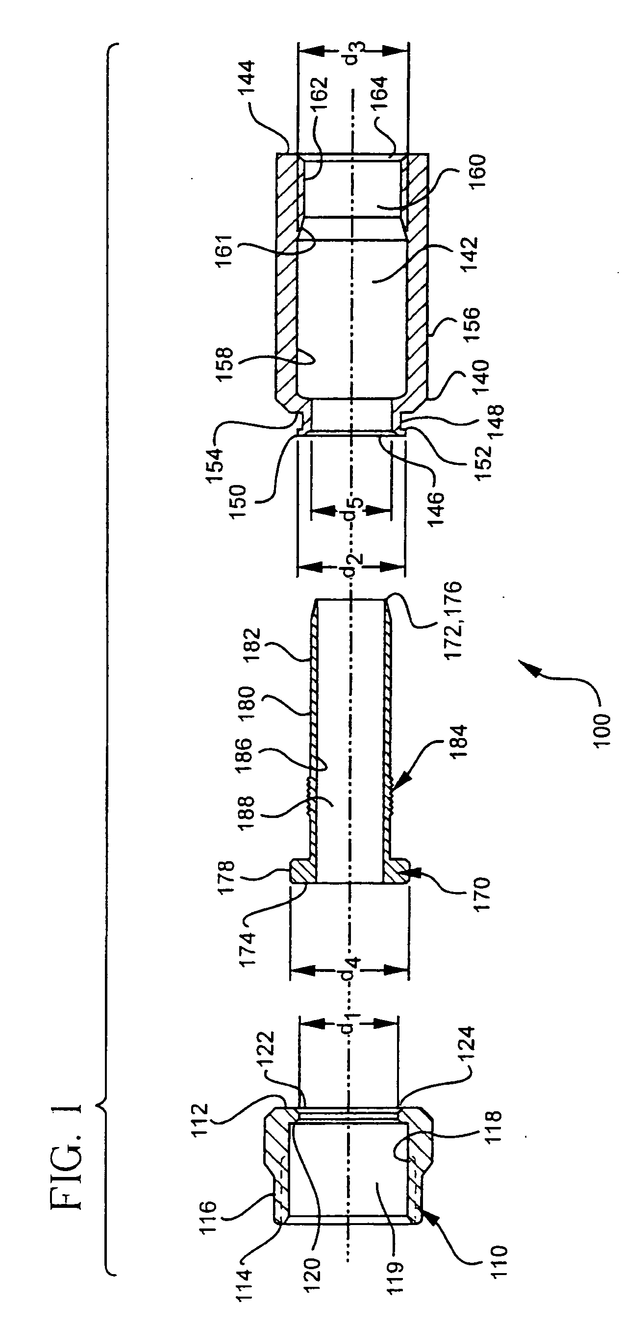
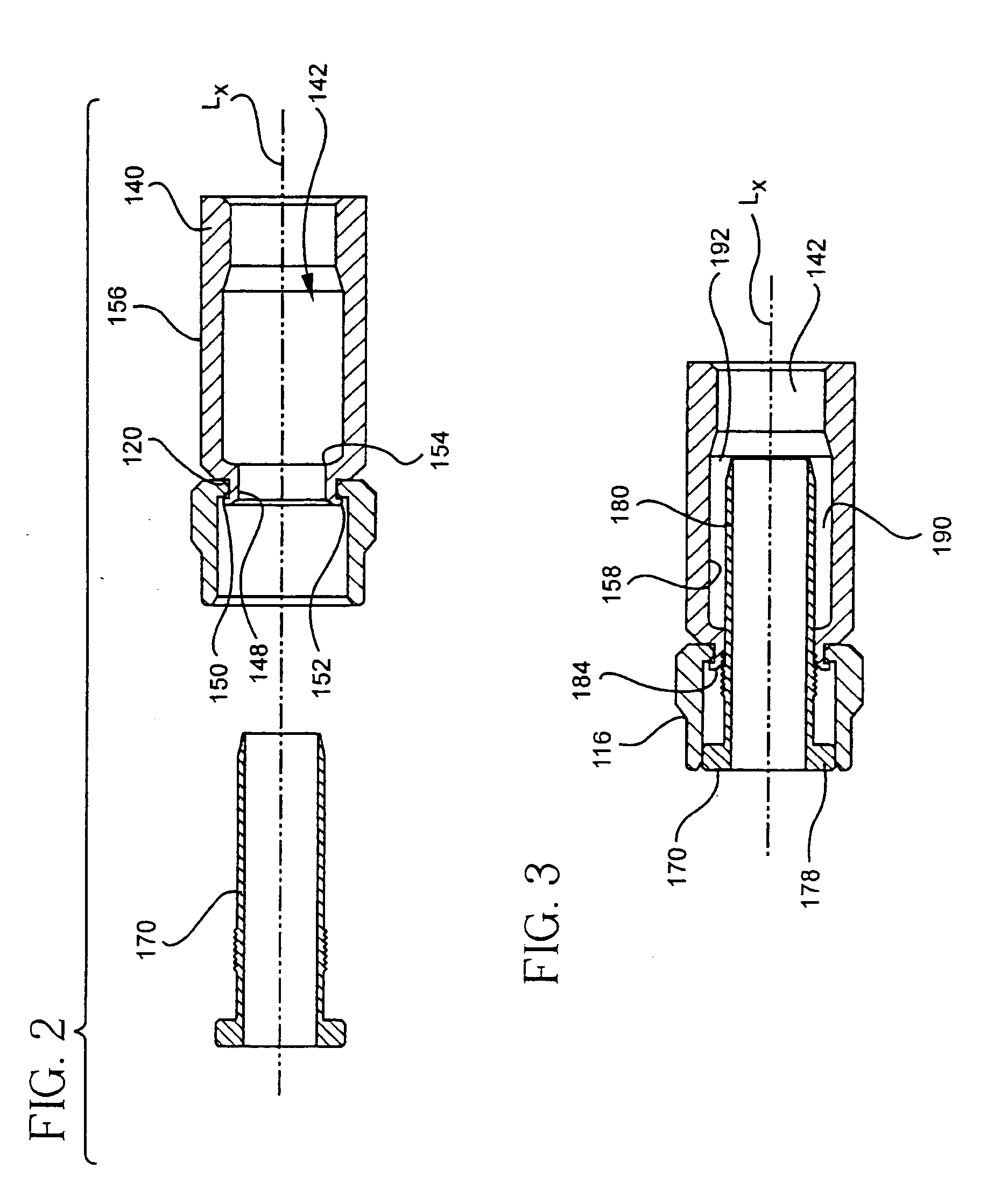
[0105] FIGS. 1-3 and 5-7 illustrate an example of a connector, generally designated by ref...


PUM


Abstract

A connector is provided for coupling an end of a coaxial cable to a terminal, such as a cable terminal, a terminal for coupling to another connector, and the like. The connector includes a coupler, such as a nut, having a receiving port for engaging the terminal. The coupler also includes an annular collar. The connector also includes a body member, one end of which includes a lip. The lip is inserted through the collar opening. The other end of the body section includes an inner surface portion. The connector still further includes a post, an end of which is sized for insertion between the dielectric and the outer conductor of the cable. The post further includes a post flange and a post shank. The post shank forms a post channel sufficient in diameter to receive the inner conductor and the dielectric of the cable. The post is movable between a cable-insertion position and a cable-installed position. In the cable-installed position, the post shank is received in the body member to form an annular chamber between the post shank and the inner surface portion. The annular chamber is sufficiently narrow in this cable-installed position to compress the outer conductor and the jacket with the post shank and the inner surface portion for establishing a distal seal. Tightening of the coupler to the terminal compresses the lip between the post flange and the annular collar for establishing a proximal seal. Related methods also are provided.

Description

[0001] This is a continuation-in-part of U.S. patent application Ser. No. 10 / 142,274 filed on May 8, 2002, the content of which is relied upon and incorporated herein by reference in its entirety, and the benefit of priority under 35 U.S.C. .sctn. 120 is hereby claimed. This application further claims the benefit of priority under 35 U.S.C. .sctn. 365 of International Patent Application Serial No. PCT / US03 / 14805 filed on May 8, 2003 designating the United States of America. This application further claims the benefit of priority under 35 U.S.C. .sctn. 119(e) of U.S. Provisional Application Serial No. 60 / 502,070 filed on Sep. 11, 2003.[0002] 1. Field of the Invention[0003] The present invention relates generally to connectors for coupling cables to terminals, or to one another, etc., and methods for assembling and using the same. More specifically, the invention relates to connectors for coaxial cables and related methods, wherein the connector can provide an environmental sealing ro...

Claims


Application Information

Patent Timeline
IPC IPC(8): H01R9/05H01R13/52
CPCH01R9/0521H01R13/5205
Inventor BURRIS, DONALD A.LUTZ, WILLIAM B.WOOD, KENNETH S.
Owner PPC BROADBAND INC
Why Eureka
Try Eureka