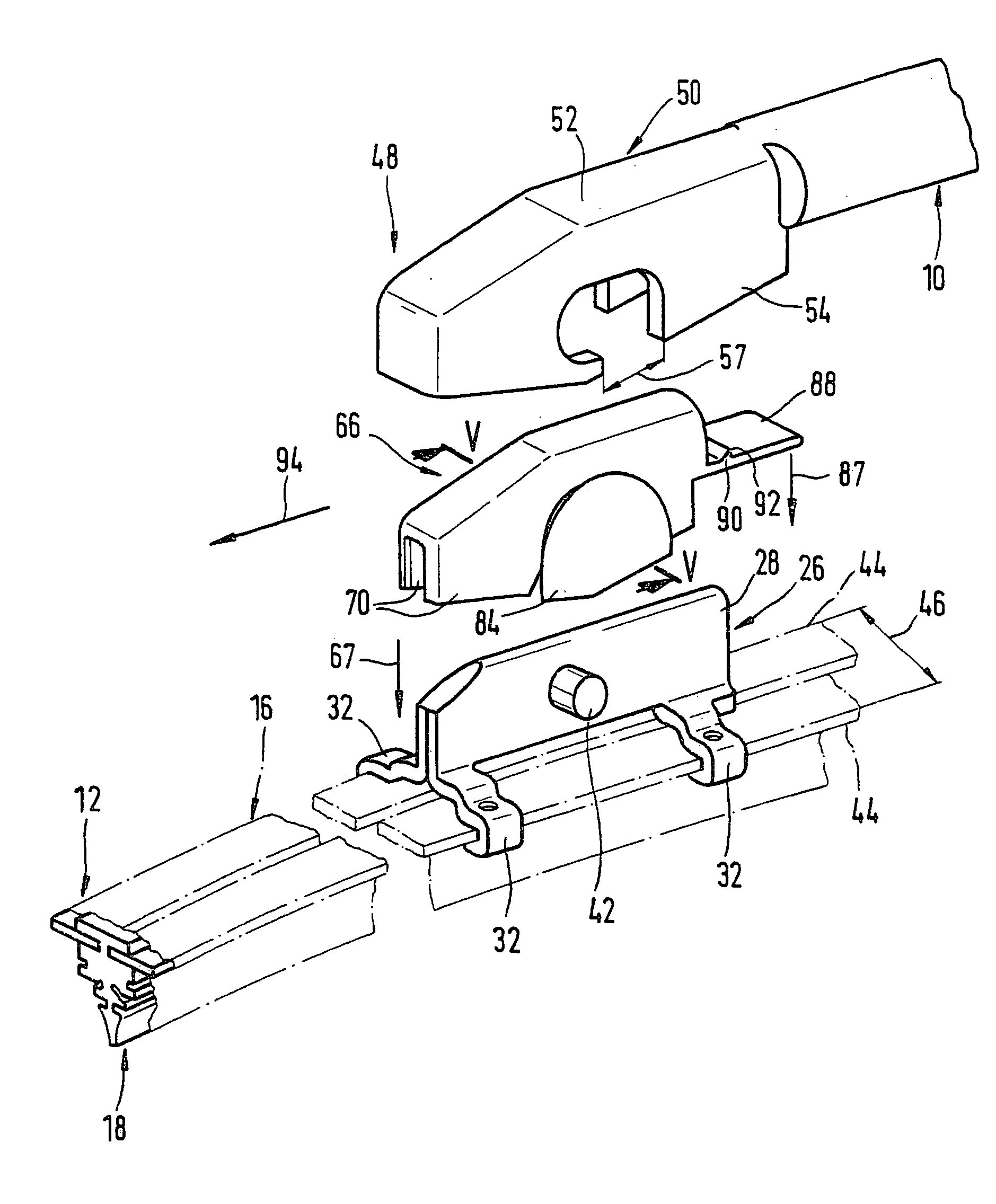
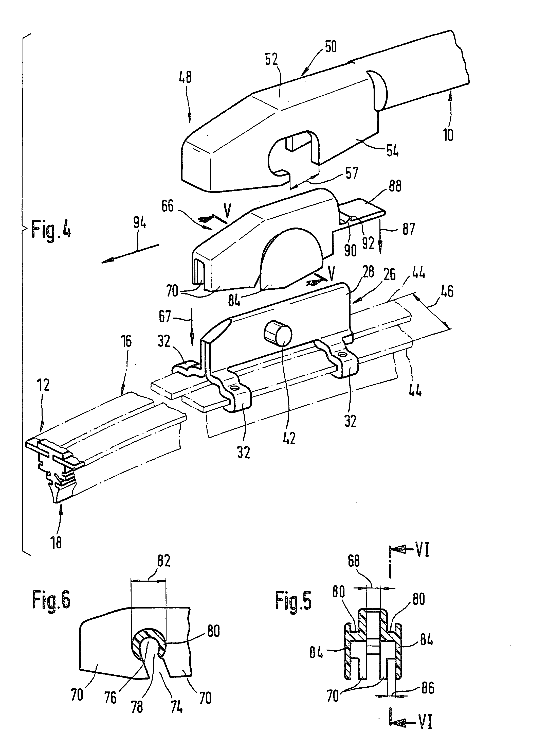
[0011] In another development of the invention where the adapter essentially has a U-shaped cross-section, whose two U-legs grip over the T-foot of the connecting element laterally so they fit, whose U-base covers the T-foot of the connecting element and in each of the two U-legs an open-edge, slot-like recess is arranged towards their free ends, whose slot ends form rest receptacles for the pivot pins, large guidance surfaces are produced between the adapter that belongs to the wiper blade and the connecting element connected to the supporting element of the wiper blade, thereby achieving a connection free of play that assures a good wiper image.
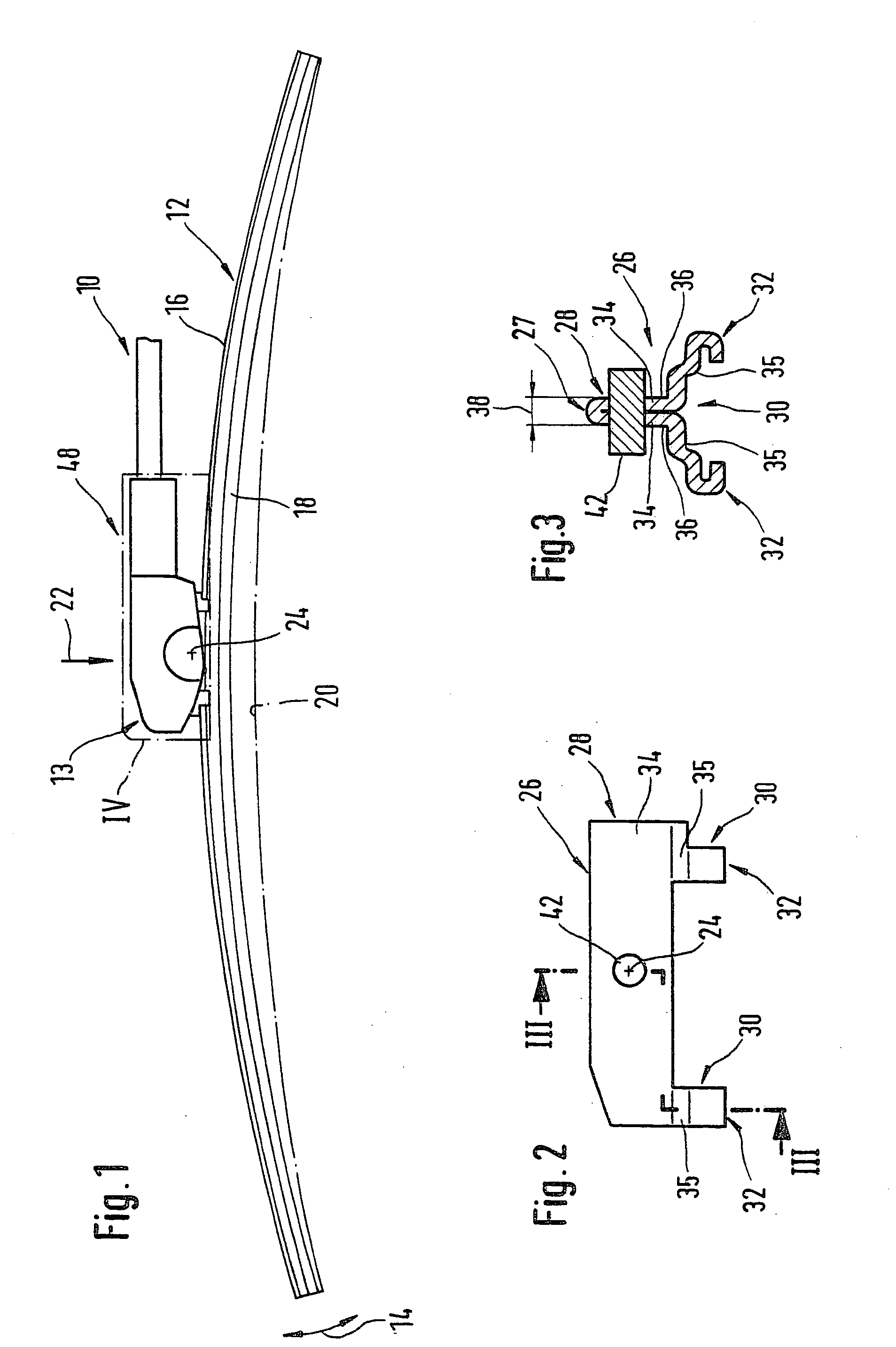
[0002] In order to connect a wiper blade embodied in this manner to the wiper arm, the wiper blade must be provided with a specially embodied connecting element, which can be used to connect it in the required manner to the wiper arm. In addition, the wall surfaces of the connecting element should provide proper guidance for the wiper blade, when it is slid from the wiper arm transverse to its longitudinal extension over the to-be-wiped window, because they are adjacent to the wiper arm's guidance surfaces. Because the normally spherically curved
windshield of a motor vehicle does not represent a section of a spherical surface, the wiper blade must be able to constantly adapt to the respective position and progression of the window surface vis--vis the wiper arm during its wiper operation. For this reason, a smooth-running articulated connection between the wiper arm and the wiper blade that enables an oscillation motion around the pivot pin axis is required.
[0005] A particularly small design of the articulated connection between the wiper arm and wiper blade and one where the connecting device does not impair vision from the passenger compartment of the motor vehicle is produced if the distance between the two wall surfaces of the connecting element is smaller than the width of the supporting element.
[0006] Thus, in accordance with a design of the invention that is particularly suited for manufacturing, the two wall surfaces of the connecting element are formed by the outside surfaces on the T-foot of a component whose cross-section is T-shaped at least in sections, and whose T-head facing the supporting element is connected to it.
[0017] An unintentional activation of the tongue in the sense of detaching the safety connection between the wiper blade and the wiper arm is avoided if the tongue is connected with at least one U-leg of the adapter on its side facing the drive side of the wiper arm and, in addition, if the locking shoulder projects on the side of the tongue facing away from the wiper blade and said locking shoulder is assigned a wiper-arm-mounted counter locking shoulder.
[0018] On the other hand, a
user friendly embodiment of the invention is produced if the tongue is arranged on the U-base of the adapter and extends towards the free end of the wiper arm, whereby the counter locking shoulder is embodied on the front side of the wiper arm and the tongue projects over the free end of the wiper arm with its locking shoulder.
[0019] In order to prevent a disadvantageous relative rocking movement around the articulated axis between the wiper arm and the adapter, it has proven to be expedient if the adapter is provided with a lateral overhang at least on one U-leg at a distance from the collar-like projections, and said overhang is assigned to a recess provided on the side cheeks of the wiper blade holder.
[0020] To protect the articulated connection from
dirt, shield-like coverings projecting laterally over the projections are arranged on the collar-like projections at a distance from the U-legs of the adapter.
[0021] The foregoing explanations therefore yield an entire series of features, which contribute to the construction of an articulated connection between the wiper arm and wiper blade that is easy to operate, cost-effective and free of play. One of the components that is required for this--namely the connecting element--is embodied in accordance with the pre-characterizing clause of claim 20. A known connecting element of this type (DE 19 72 98 64.8A1) features an articulated bolt on only one side of the T-foot for connecting to the wiper arm. This therefore results in an articulated connection placed outside the longitudinal middle axis of the wiper blade, which can prove to be disadvantageous with respect to the application force originating from the wiper arm in the case of certain window configurations. In this case, the two wall surfaces of the T-foot that face away from one another also do not serve as guidance surfaces, which cooperate with corresponding counter surfaces of the wiper arm during wiper operation. In this case, wiper blade guidance is assumed alone by the small-surface, one-sided ring collar of the articulated bolt. However, if the
structural element is developed in accordance with the characterizing features of claim 20, the application force originating from the wiper arm will be transmitted uniformly on both pins and excellent wiper blade guidance will also be achieved during wiper operation Additional advantageous further developments and designs of the invention are disclosed in the following description of the exemplary embodiments depicted in the associated drawing.

