Passive safety device

a safety device and pass-through technology, applied in the direction of vehicle body, roof, monocoque construction, etc., can solve the problems of severe leg lesions, severe lesions, and rigid structur

Inactive Publication Date: 2004-11-04
CO PLASTIC OMNIUM
View PDF16 Cites 12 Cited by
  • Summary
  • Abstract
  • Description
  • Claims
  • Application Information

AI Technical Summary

Benefits of technology

[0023] Thus, by means of the invention, in the event of a head-on collision with a pedestrian, the block compresses, thereby providing resistance which is initially very small at the moment of impact and then rises progressively and continuously while the shield is being indented. This results in the force to which the pedestrian is subjected being spread out, thereby having the effect of minimizing injuries.
[0026] Thus, by means of this bottom portion, which optionally constitutes a restrainer, in the event of an impact, the pedestrian's knee comes initially into contact with the top portion of the shield which indents progressively in the manner explained above, until the pedestrian's leg comes over the bottom portion at the moment it comes into contact with the beam. During an impact, this has the effect of keeping the pedestrian's leg substantially upright, thereby avoiding any risk of the pedestrian going under the vehicle.
[0030] This shape makes it simple to implement the above-described increase in section for causing the force applied to a pedestrian by the bumper to increase progressively. This shape also makes it simple to obtain a front face that is to be in register with the tibia of a pedestrian and a rear face that is to be in register with both the tibia and the knee.

Problems solved by technology

The problem with that type of bumper lies in the structure being too rigid.
Another problem with such bumpers consists in the way the force (F) suffered by a pedestrian as a function of the extent (e) to which the pedestrian is pushed into the shield is at a maximum (F=F.sub.MAX) at the moment of impact between the vehicle and the pedestrian, as can be seen from the graph of FIG. 1b.
Consequently, the impact suffered by the pedestrian leads to severe lesions of the legs, even if the impact takes place at low speed.
As can be seen in the graphs of FIGS. 2b and 3b, the problem with such absorption means lies in the way the force suffered by a pedestrian in the event of a head-on collision is at a minimum (F=F.sub.MIN) at the moment of impact, and passes instantaneously to a maximum value (F=F.sub.MAX) once the shield becomes pressed against the beam.
Consequently, a pedestrian suffering a head-on collision with a bumper of the above-described type will be subjected to a strong force against the leg, and in particular against the knee, and that can lead to severe lesions.
These lesions can be the result both of impact proper and of the leg bending excessively about the knee.
Thus although the safety of vehicle passengers has been improved, the problem consists in improving the safety of pedestrians by avoiding lesions at the level of a pedestrian's knee, a zone that is particularly fragile and difficult to treat, and to do so by making impact as non-violent as possible.
Firstly it distributes the force suffered by the leg over two impact zones, and secondly in the event of a collision with a pedestrian, it prevents the bottom of the pedestrian's tibia from passing under the vehicle, thereby restricting the angle to which the leg is bent.
Nevertheless, the problem with such low restrainers lies in imposing a particular appearance on the bumpers of the vehicle.
Such a constraint can degrade the attractiveness of the vehicle.

Method used


Image

  • Passive safety device
  • Passive safety device
  • Passive safety device

Examples


Embodiment Construction

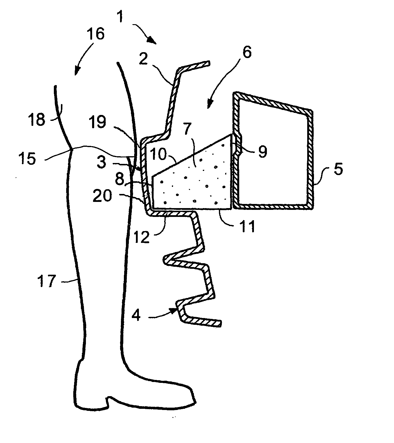
[0042] FIG. 4a shows a motor vehicle bumper 1. The bumper 1 comprises a shield 2, also referred to as a bumper "skin", extending transversely between the fenders of the vehicle, and performing a function that is essentially decorative.

[0043] The bumper 1 also comprises a beam 5 placed transversely behind the shield 1, in register therewith and at a certain distance therefrom, so as to leave a space 6 between them in which there is placed a block 7 that is interposed between the shield 2 and the beam 5.

[0044] FIG. 4a also shows, in front of the bumper 1, the leg 16 of an adult pedestrian of medium size, on the point of being subjected to an impact with the vehicle. The leg shown comprises the knee 15, the tibia 17, and the femur 18 of the pedestrian. As required by standards, it is assumed that the knee 15 of the pedestrian is situated at 500 mm above the ground.

[0045] The beam 5 of the vehicle is arranged in register with two side rails of the vehicle (not shown) which corresponds s...


PUM


Abstract

The invention provides a motor vehicle bumper comprising: a shield presenting a first impact zone situated substantially at the same height as the knee of an adult pedestrian and, immediately below said first zone, a second impact zone situated substantially at the height as the tibia of an adult pedestrian; a beam placed behind the shield substantially at the same height as the knee of an adult pedestrian, in register with and at a certain distance from the shield; and interposed between the beam and the shield, at least one block made of a compressible material, the block having a front end disposed beside the shield and a rear end disposed beside the beam, and having a cross-section that increases from its front end towards its rear end. The front end of the block is disposed in register with the second impact zone of the shield.

Description

[0001] Until recently, manufacturers were concerned essentially with the safety of passengers in a vehicle.[0002] Numerous solutions have appeared for that purpose consisting in designing bumpers and in stiffening the external structure thereof so as to form a barrier for protecting the vehicle cabin.[0003] Such bumpers generally comprise a shield, also referred to as a bumper "skin", acting essentially to provide decoration, but also serving to absorb impacts of small amplitude. Bumpers also comprise one or more beams extending transversely behind the shield and forming a barrier to protect the vehicle cabin. In general, the beam is placed at the same level as the side rails of the vehicle, a height which corresponds substantially to the height of the knee of an adult pedestrian passing in front of the vehicle.[0004] In order to preserve the vehicle cabin and thus its passengers as well as possible, it was considered a few years ago that the structure of the vehicle and thus of the...

Claims


Application Information

Patent Timeline
Patent Type & Authority Applications(United States)
IPC IPC(8): B60R19/18B60R21/34
CPCB60R19/18B60R21/34B60R2019/1873B60R2019/1893
Inventor BANRY, PASCALROUSSEL, THIERRYCHAAYA, RIAD
Owner CO PLASTIC OMNIUM
Why Eureka
Try Eureka