
Systems and methods for a portable walk-through metal detector

a metal detector and portable technology, applied in the field of walk-through metal detectors, can solve the problems of limiting the ability of the detector to operate, requiring additional equipment to make them mobile, and difficult to move to various locations

Active Publication Date: 2004-11-04
FISHER RES LABS LLC
View PDF9 Cites 9 Cited by
  • Summary
  • Abstract
  • Description
  • Claims
  • Application Information

AI Technical Summary

Benefits of technology

[0019] In accordance with yet another aspect of the present invention, the sensor panels have windowed areas to reduce weight, reduce wind resistance, and provide visibility into the walk through archway.
[0020] In accordance with a further aspect of the present invention, the metal detector is in a weatherproof package that facilitates outdoor use.
[0021] In accordance with yet another aspect of the present invention, the portable walk through metal detector operates from an optional solar power system, allowing continuous outdoor usage.

Problems solved by technology

The main problem with conventional walk through metal detectors is that they are heavy and difficult to move to various locations.
Another problem with conventional walk through metal detectors is that they require additional equipment to make them mobile.
Another problem with conventional walk through metal detectors is the power consumption of the electronic system limits the detectors ability to operate from a battery source for more than a few hours, requiring AC power to be accessible for either operation, or frequent battery recharging.
While these devices may be suitable for the particular purpose to which they address, they are not as suitable as a portable walk through metal detector with interchangeable sensor panels and other structural members that can be quickly assembled, or disassembled and transported.
The main problem with conventional walk through metal detectors in portable applications is that they are heavy and difficult to move to various locations.
Generally, conventional metal detectors' parts are too big to fit in an automobile.
Also, another problem is the power consumption of the electronic system limits the detectors ability to operate from a battery source for more than a few hours, requiring AC power to be accessible for either operation, or frequent battery recharging.

Method used


Image

  • Systems and methods for a portable walk-through metal detector
  • Systems and methods for a portable walk-through metal detector
  • Systems and methods for a portable walk-through metal detector

Examples


Embodiment Construction

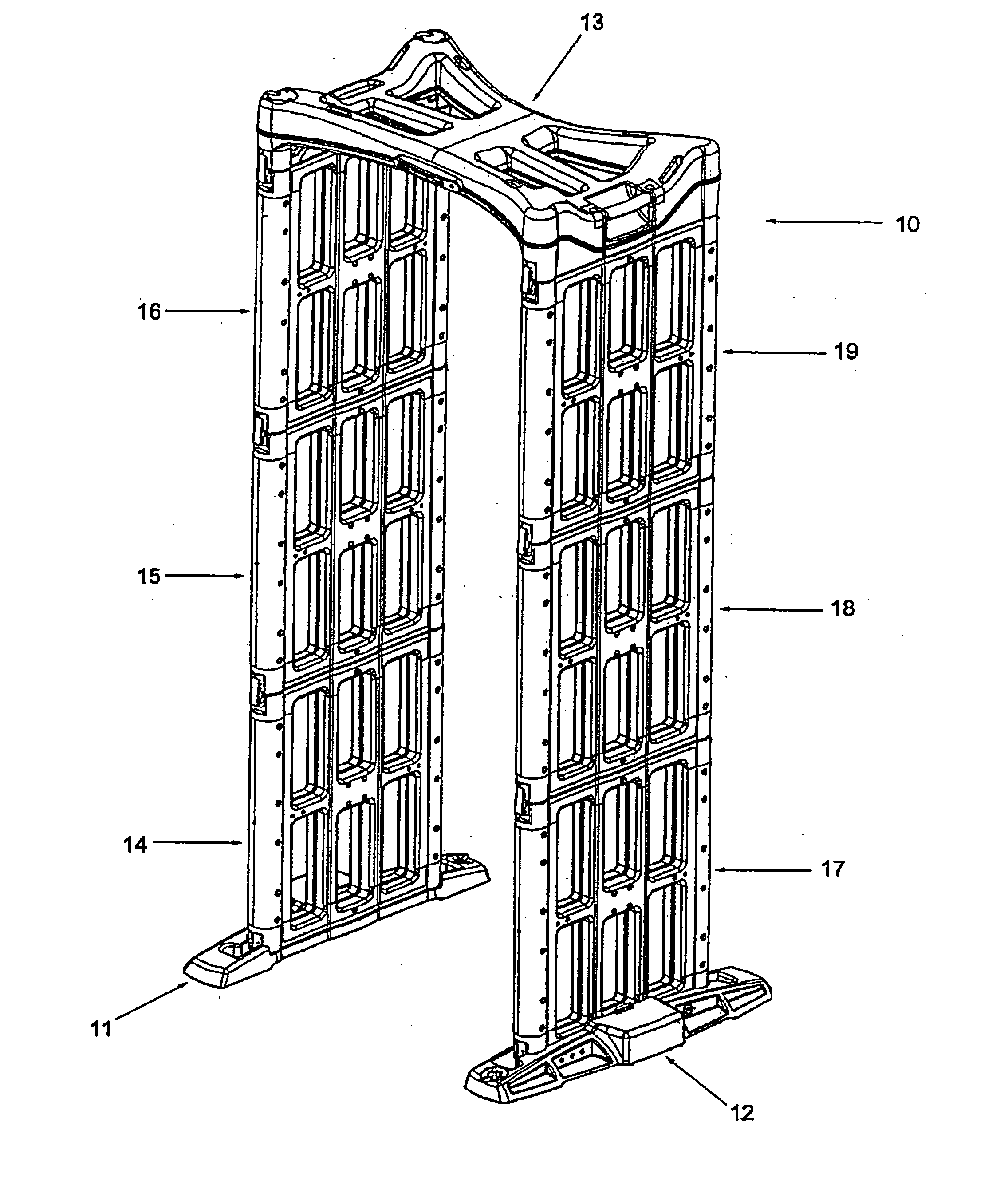
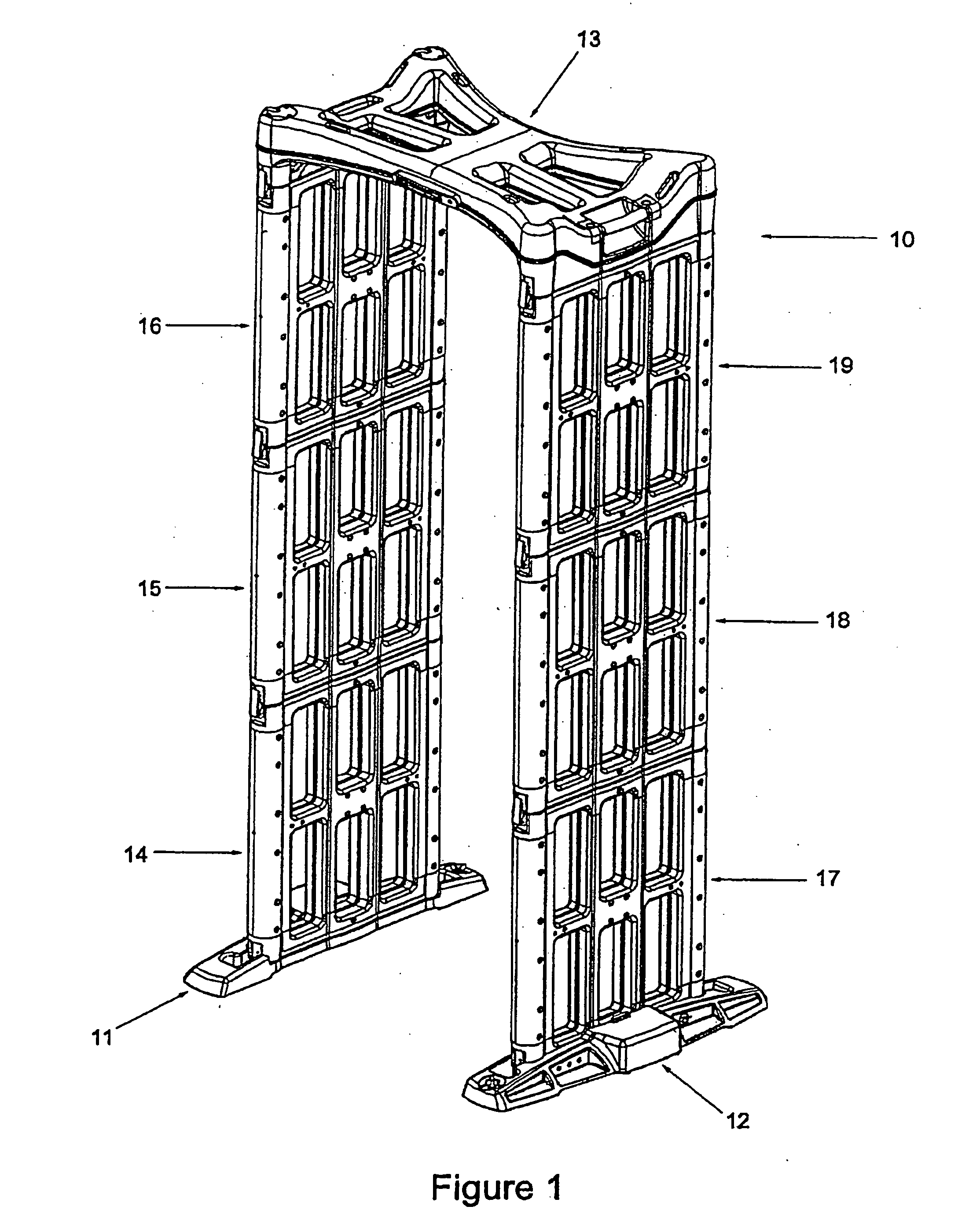
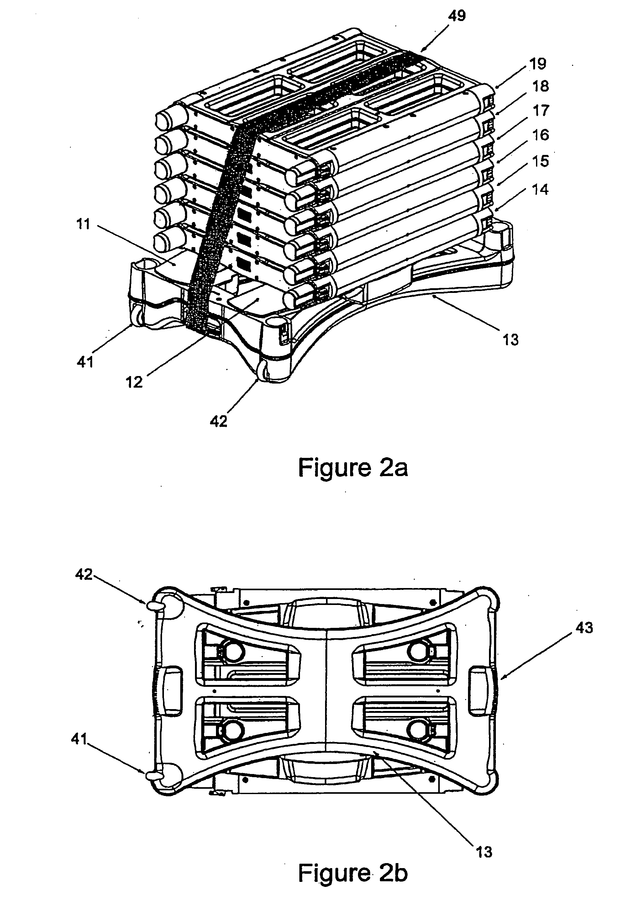
[0034] Turning now descriptively to the drawings, in which similar reference characters denote similar elements throughout the several views, the attached figures illustrate a walk through metal detector and method with portable construction wherein the same can be utilized for rapid assembly, or disassembly and transport, which comprises of two structural base members to anchor the archway, multiple sensor panels with which the sides of the archway are constructed, and a top cross-member to join and support the walls of the archway. The base members consist of a housing to provide contact with the ground, mechanical hardware and fittings to facilitate mounting of the sensor panels, rechargeable batteries to provide the system power source, and electronic connectors to pass signals from the base section to adjacent sensor panels. The sensor panels consist of a housing to provide structure for the sensor coils and electronics, mechanical hardware and fittings to facilitate mounting o...


PUM


Abstract

A portable walk through metal detector with interchangeable sensor panels and other structural members that can be quickly assembled, or disassembled and transported. The device includes two structural base members to anchor the archway, multiple sensor panels with which the sides of the archway are constructed, and a top cross-member to join and support the walls of the archway. In addition, the top cross-member provides a vehicle platform for moving a disassembled unit with built-in wheels, a handle, and stacking structures to support the other members.

Description

CROSS-REFERENCES TO RELATED APPLICATIONS[0001] This application is a non-provisional application and claims the benefit of Application No. 60 / 466,839, filed Apr. 29, 2003, entitled "Portable Walk Through Metal Detector and Method," which disclosure is hereby incorporated herein by reference for all purposes.STATEMENT AS TO RIGHTS TO INVENTIONS MADE UNDER FEDERALLY SPONSORED RESEARCH OR DEVELOPMENT[0002] NOT APPLICABLEREFERENCE TO A "SEQUENCE LISTING," A TABLE, OR A COMPUTER PROGRAM LISTING APPENDIX SUBMITTED ON A COMPACT DISK.[0003] NOT APPLICABLE[0004] 1. Field of the Invention[0005] The present invention relates generally to walk through metal detectors for security applications and more specifically it relates to a portable walk through metal detector and method with interchangeable sensor panels and other structural members that can be quickly assembled, or disassembled and transported.[0006] 2. Description of the Prior Art[0007] Walk through metal detectors have been in use for...

Claims


Application Information

Patent Timeline
IPC IPC(8): G01V3/10
CPCG01V3/104
Inventor CASTLE, JONATHANJONES, MARVIN E.
Owner FISHER RES LABS LLC
Learn More