Method and device for measuring heart rate, and method for manufacturing the device

Active Publication Date: 2004-11-04
POLAR ELECTRO
View PDF15 Cites 45 Cited by
  • Summary
  • Abstract
  • Description
  • Claims
  • Application Information

AI Technical Summary

Benefits of technology

0010] The invention is based on providing a measuring device with an electrically conductive outer surface for heart rate measurement on opposite sides of a hand to which the device is attached. This enables a firm and convenient grip to be taken both of the measuring device and the hand to which it is attached.
0011] The solution of the invention provides a number of advantages. The contact made by both hands becomes reliable and contact impedance is reduced, due to increased contact surface between the measuring device and the skin as a result of an increase in

Problems solved by technology

However, this kind of measurement involves a number of problems.
The forces acting between the hands thus vary considerably, particularly during motion, which impairs the measurement contact, the quality of the detected EKG signal, and thereby also the measurement result.
Moreover

Method used


Image

  • Method and device for measuring heart rate, and method for manufacturing the device
  • Method and device for measuring heart rate, and method for manufacturing the device
  • Method and device for measuring heart rate, and method for manufacturing the device

Examples


Embodiment Construction

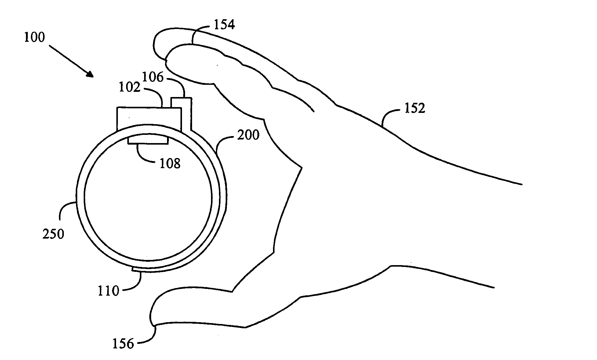
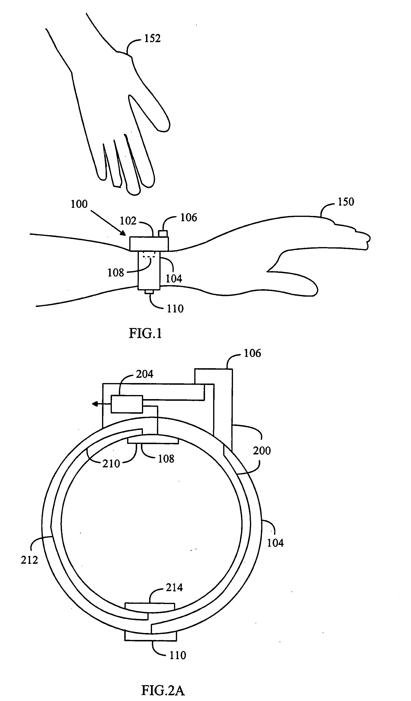
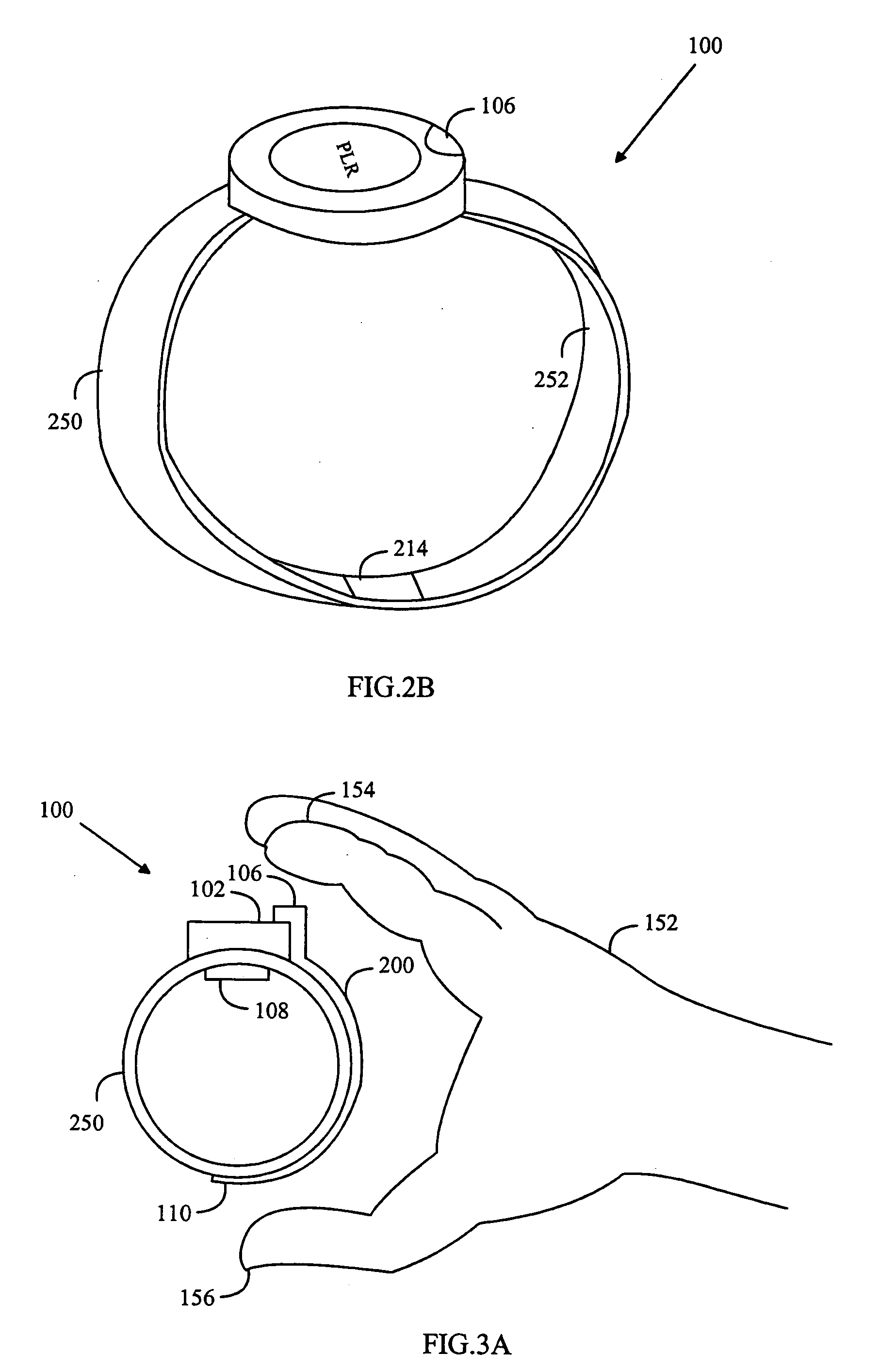
[0022] The disclosed solution will be first examined with reference to FIG. 1. A measuring device 100 is attached to a user's hand 150 in the same way as a wristwatch. The measuring device 100 is usually attached to the wrist, although the exact position of the device on the hand is not relevant to the disclosed solution, only the fact that the measuring device 100 can be attached to one of the user's hands 150. The measuring device 100 of the disclosed solution comprises a measuring unit 102 and attaching means 104. The attaching means 104 with which the measuring device 100 is attached to the user's arm may be similar to the wristbands of wristwatches. The measuring unit 102 is usually a heart rate monitor or a wrist computer and it comprises a casing containing for example signal processing means for electric processing of signals, a display for displaying information, and a user interface (these being not shown in FIG. 1). The measuring device has electrodes 106 and 110 on oppos...


PUM


Abstract

A heart rate measuring device is attached around a user's hand, the device having an inner surface, which is in contact with the skin on the hand to which it is attached, and an outer surface, which is other than the inner surface. The inner surface of the measuring device is provided with an electrically conductive inner structure, which functions as an electrode for a contact with the skin of the hand to which the device is attached. An electrically conductive outer structure functions as an electrode for a contact with the user's other hand and it is electrically isolated from the electrically conductive inner structure. The electrically conductive outer structure on the measuring device extends at least to opposite sides of the hand to which the device is attached, and at least part of the electrically conductive outer surface is on the outer surface of the measuring device, on opposite sides of the hand to which the device is attached. The electrically conductive outer structure and inner structure are connected to a measuring unit for heart rate measurement.

Description

FIELD[0001] The invention relates to a measuring device and a measuring method arranged to measure non-invasively the heart function of a user on whose hand the measuring device has been attached.[0002] Heart rate measurement is based on monitoring the function of the heart. When the heart contracts it causes a series of electric impulses that can be measured in the body. The measurement and analysis of this signal is called electrocardiography (EKG), and the signal itself is known as an EKG signal. Different phases of the heart cycle can be distinguished in the signal.[0003] Heart rate can be measured with a measuring device similar to a wristwatch, for example, the device measuring an EKG signal from the user's hands. The measuring device comprises a measuring unit that may contain for example an electronic signal processing unit for processing the EKG signal, a display, a user interface, and a wristband portion for attaching the measuring device to the user's hand. The inner meas...

Claims


Application Information

Patent Timeline
IPC IPC(8): A61B5/024A61B5/0245A61B5/0408
CPCA61B5/02438A61B5/0245A61B5/04085A61B5/681A61B5/282
Inventor RYTKY, PEKKA
Owner POLAR ELECTRO
Why Eureka
Try Eureka