Active electromagnetic device for measuring the dynamic response of a tool in a CNC machine

a technology of electromagnetic device and dynamic response, which is applied in the field of cnc (computer numerical control) programming and machining, can solve the problems of high speed, inability to achieve cnc machines at high speeds, and inability to test and interpr

Inactive Publication Date: 2004-11-25
ESTERLING DONALD M
View PDF4 Cites 26 Cited by
  • Summary
  • Abstract
  • Description
  • Claims
  • Application Information

AI Technical Summary

Problems solved by technology

These tests and their interpretation could not be expected of a typical shop floor machinist.
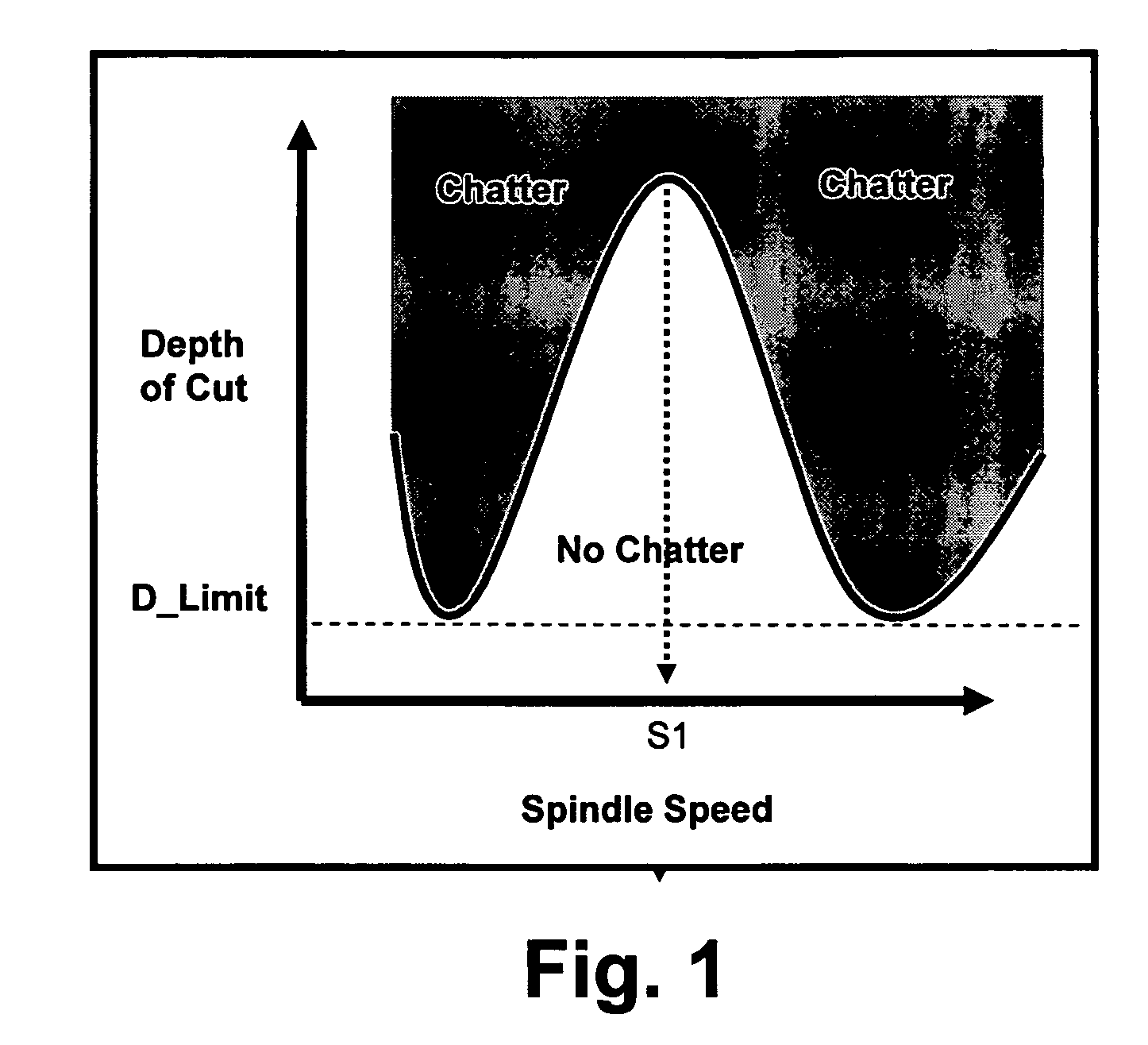
The best cutting speeds determined with the Davies device may be, and often are, exceptionally high speeds and are not attainable for many CNC machines.
In addition, since the Davies device provides no guidance on the stable depths of cut at these or any other spindle speeds, the operator must determine the stable, chatter-free depths of cut by trial and error.

Method used


Image

  • Active electromagnetic device for measuring the dynamic response of a tool in a CNC machine
  • Active electromagnetic device for measuring the dynamic response of a tool in a CNC machine
  • Active electromagnetic device for measuring the dynamic response of a tool in a CNC machine

Examples


Embodiment Construction

[0080] A test version of the present invention was developed for a milling environment.

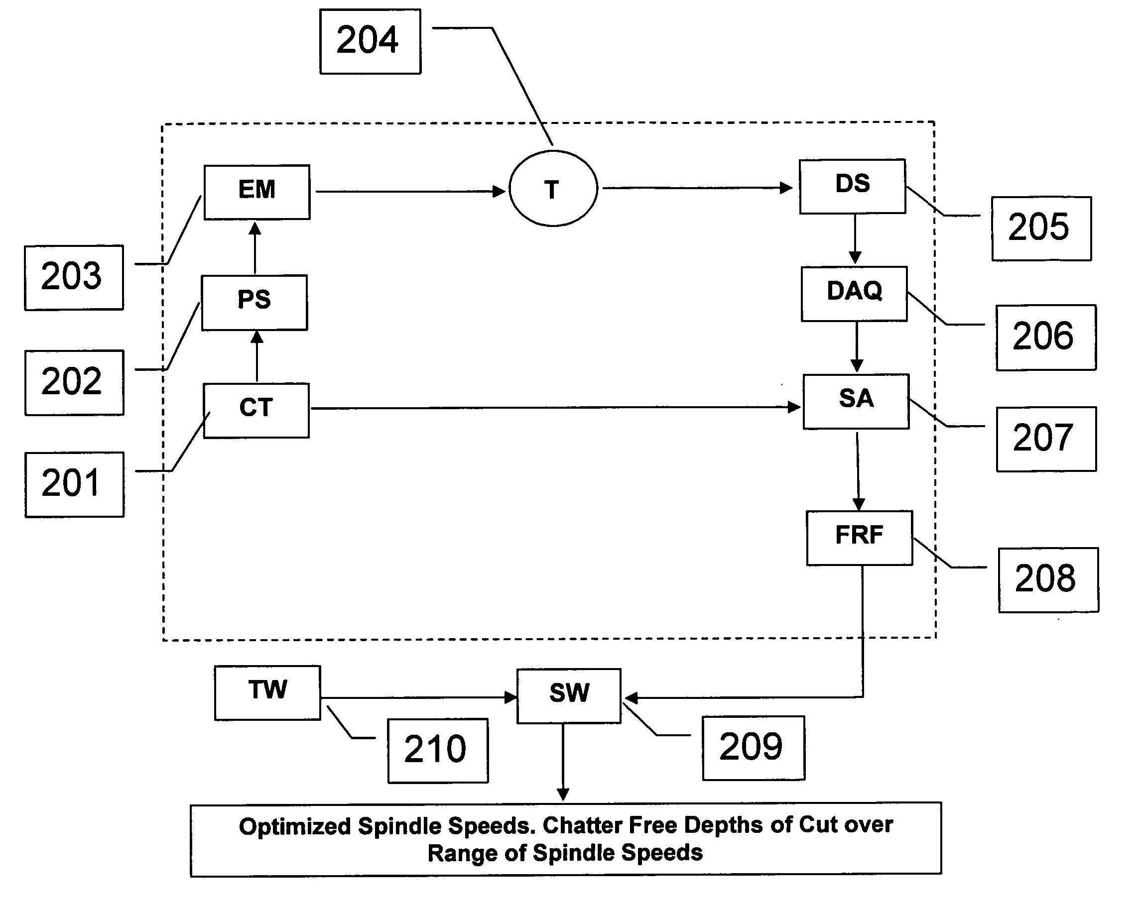
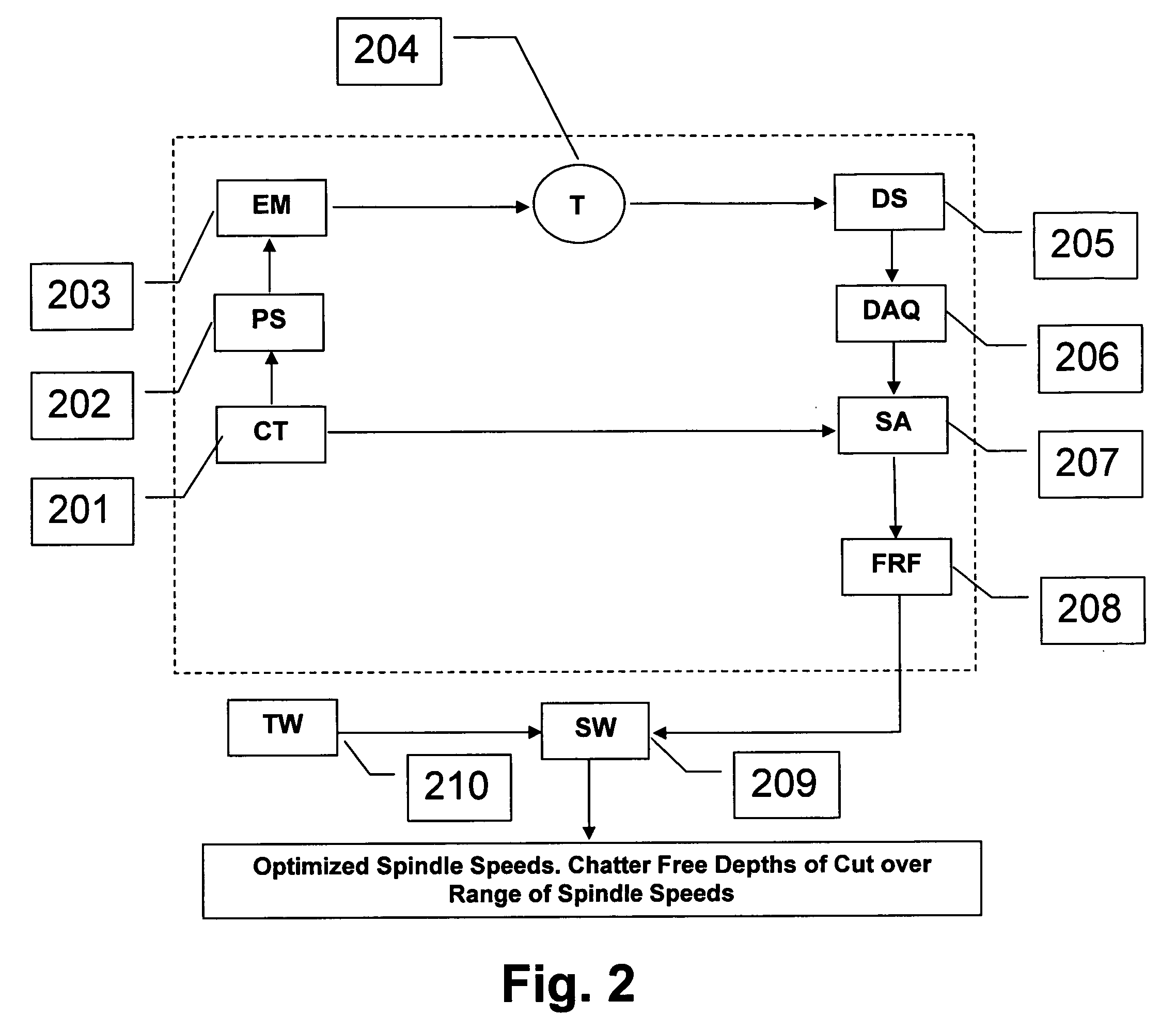
[0081] The test version consisted of a tool sited in a CNC machine, an electromagnetic actuator, voltage detectors, a power supply, a controller board to control the power output to the actuator and a user interface device. The later informs the user when the tool is properly sited relative to the electromagnetic actuator, starts the measurement process and records the data. The user interface device for the example was a laptop computer.

[0082] FIG. 3 is a schematic planar cross-sectional view of the device. The electromagnet 101 is driven by an alternating current applied to a wire coli 102. The electromagnet induces a force on a magnetically active tool 103, causing a displacement which is measured by a sensor 104. The force applied to the tool 103 is controlled by the current supplied to the coil 102. By applying currents with different frequency profiles to the electromagnet, a frequency depen...


PUM

PropertyMeasurementUnit
frequencyaaaaaaaaaa
lengthaaaaaaaaaa
resonant frequencyaaaaaaaaaa

Abstract

The present invention provides a device for determining the dynamics of a tool sited in a CNC machine, as encapsulated by the Frequency Response Function. The device uses an actively controlled electromagnet to excite forces on the tool. The force is excited in a non-contact manner, allowing the force to be applied to both a stationary and a rotating tool. The displacement is measured by standard means, such as accelerometers, optical displacement or capacitance sensors. The ratio of the force and the displacement in the frequency domain is the Frequency Response Function. The force may be applied as a pure sine wave, providing the Frequency Response Function at the frequency of the sine wave. Varying the frequency of the sine wave provides the Frequency Response Function over the range of frequencies of interest. The control of the force profile is handled entirely by the automated controls and requires no special skills, training or manual interaction by the user. No separate force sensor is required, since the electromagnetic force on the tool may be accurately determined from the design of the electromagnet and the tool position, geometry and material.

Description

[0001] The present application is entitled to the benefit of U.S. Provisional Application No. 60 / 456,948 filed Mar. 25, 2003, the entire disclosures and contents of which are hereby incorporated by reference.[0002] Common Abbreviations and Terms[0003] The following are abbreviations and terms that will be used in portions of this application. For convenience, the abbreviations and terms are collected here for reference. Details on the particular meaning of each term may be found at the first use of the term.[0004] CNC Computer Numerical Control[0005] Type of machine tool whose operation is controlled by a computer. May also refer to the control itself or to the programming language used by the control.[0006] FRF Frequency Response Function[0007] Linear relation between an applied force and the resulting system displacement, expressed in the frequency domain.[0008] Field of the Invention[0009] This invention relates to generally to CNC (computer numerical control) programming and mac...

Claims


Application Information

Patent Timeline
Patent Type & Authority Applications(United States)
IPC IPC(8): G05B19/4065G06F19/00
CPCB23Q17/0976B23Q17/12G05B19/4065Y10T409/303752G05B2219/37434G05B2219/37534G05B2219/37228
Inventor ESTERLING, DONALD M.
Owner ESTERLING DONALD M
Why Eureka
Try Eureka