
Hollow profile

a hollow profile and profile technology, applied in the field of hollow profiles, can solve the problems of reducing material strength, unable to obtain side walls of grooves, and torsional load the hollow profile can withstand

Active Publication Date: 2004-12-02
HILTI AG
View PDF5 Cites 5 Cited by
  • Summary
  • Abstract
  • Description
  • Claims
  • Application Information

AI Technical Summary

Benefits of technology

[0010] Another object of the present invention is to provide a hollow profile that can be produced simply and economically.
[0015] Advantageously, at least one groove is provided on each of the walls of a hollow profile. On a wall of a hollow profile, several grooves can be formed next to each other. Preferably, all of the grooves have the same profile, i.e., the same depth and the same width. With an inventive hollow profile designed for use in an assembly system, with grooves having the same profile or shape, a greater flexibility in the use of the hollow profile is obtained.
[0018] Preferably, the flat material for forming the inventive hollow profile is a sheet metal that, preferably, is subjected to a rolling and bending process in order to obtain the profile. Flat material in form of sheet metal is treated easily and economically. By using a rolling / bending process, a plurality of different profiles can be formed.
[0027] Preferably after pressing backward the projecting, in the cross-section of the groove, material, in a further step, the groove bottom is straightened. Dependent on the construction of the device for forming the groove, during different operational steps, large deviations of the groove dimensions, which lie outside of predetermined tolerances, takes place. With straightening of the groove bottom, the tolerances are limited to acceptable values. According to an alternative method of forming the groove, the groove is supported, during the backward pressing of the projecting material, sidewise and beneath, e.g., by rolls or other supports, which permits to eliminate the secondary straightening of the groove bottom.

Problems solved by technology

However, the greater is the depth of the groove the smaller is the torsional load a hollow profile can withstand.
The drawback of this general rule consists in that with a small groove depths, which are accompanied by small bending radii, it is impossible to obtain side walls of a groove which would extend perpendicular to the groove bottom or to the outer side of a profile.
This leads to formation of fissures and / or reduction of the material strength.
However, this results in reduction of the cross-section of the material and, consequently, in reduction of the material strength.
Further, the connection part cannot be lifted off the groove despite side forces acting on the connection part.
With straightening of the groove bottom, the tolerances are limited to acceptable values.

Method used


Image

  • Hollow profile
  • Hollow profile
  • Hollow profile

Examples


Embodiment Construction

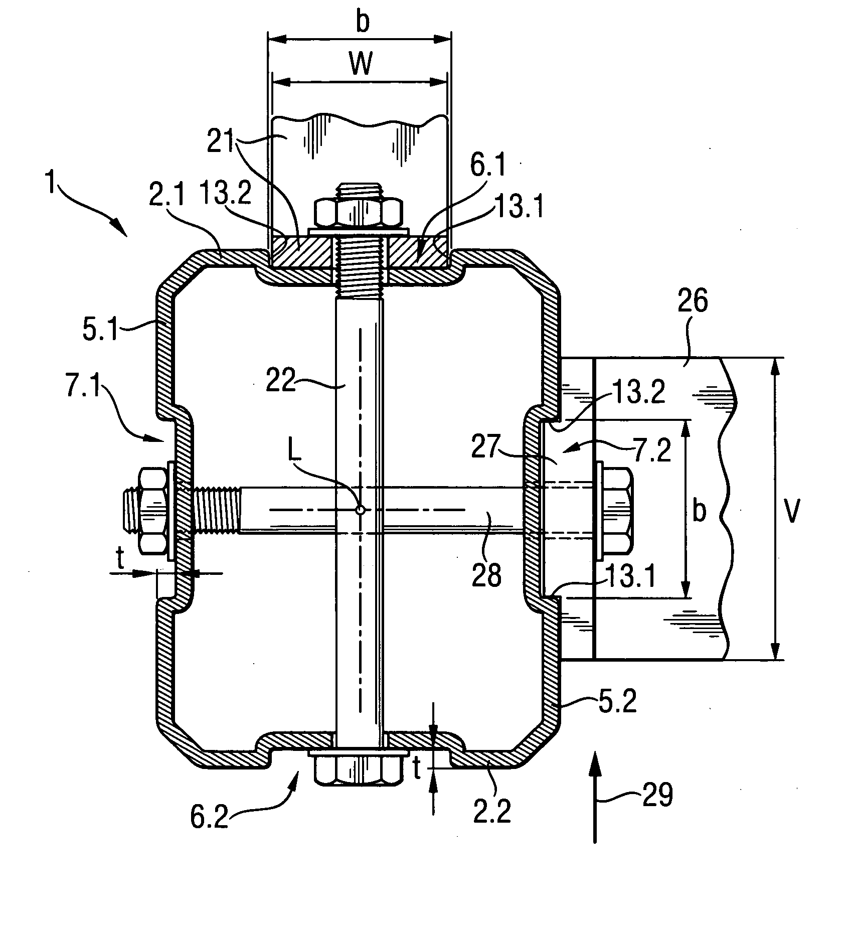
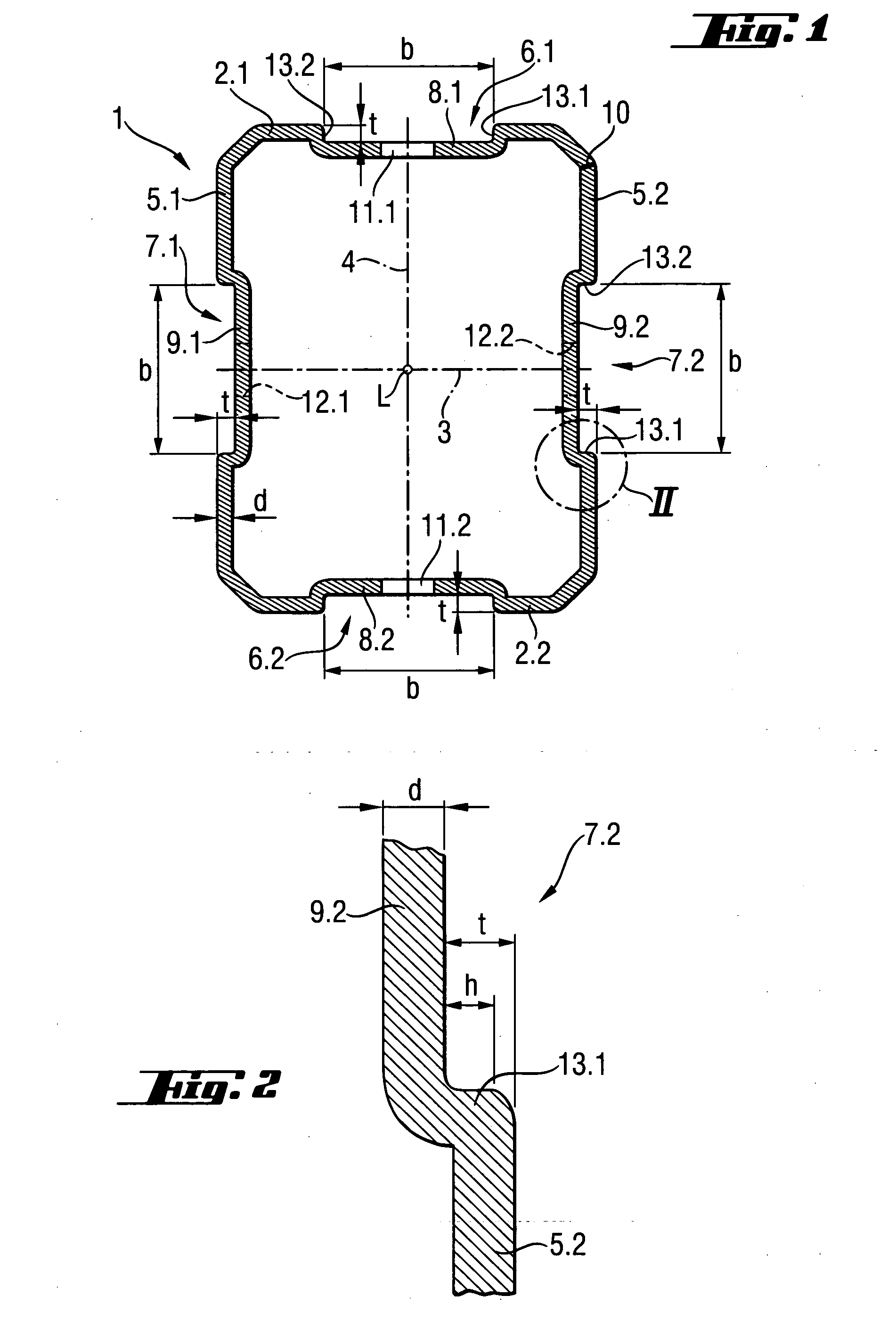
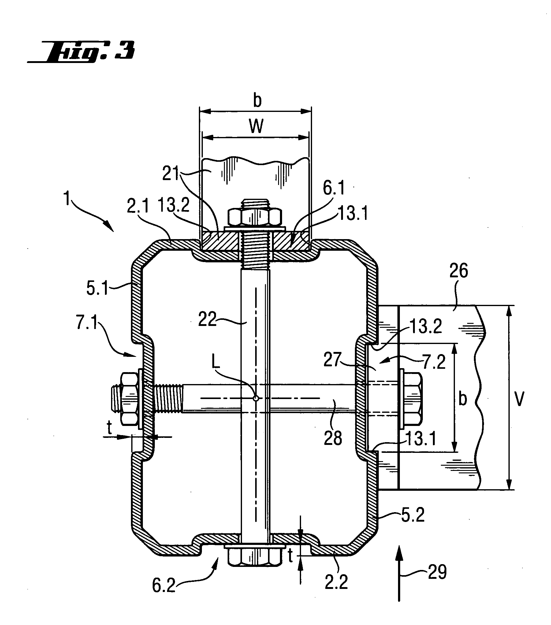
[0035] A hollow profile 1 according to the present invention, which is shown in FIG. 1, has a substantially rectangular cross-section, a first pair of side walls 2.1 and 2.2 which extend parallel to each other and to one of the axes 3 of the cross-section of the profile 1, and a second pair of side walls 5.1 and 5.2 which also extend parallel to each other and to another of the axes 4 of the cross-section of the profile 1. In the embodiment shown in FIG. 1, the hollow profile 1 has a smaller dimension in the direction of the axis 3 than in the direction of the axis 4. The hollow profile 1 is formed of sheet steel by rolling / bending process, and it has a uniform thickness d. The treated and profiled sheet steel has its opposite end surfaces connected by a butt-joined weld 10, forming a hollow profile 1.

[0036] On the side walls 2.1 and 2.2, there are formed, respectively, grooves 6.1 and 6.2 extending in the longitudinal direction L, and on the side walls 5.1 and 5.2, there are formed...


PUM

PropertyMeasurementUnit
angleaaaaaaaaaa
shapeaaaaaaaaaa
widthaaaaaaaaaa

Abstract

A hollow profile (1) formed of a flat material (31) having a width (d) has at least one groove (6.1, 6.2, 7.1, 7.2) provided on an outer side of at least one of the plurality of walls (2.1, 2.2, 5.1, 5.2) of the profile (1) and having a bottom (8.1, 8.2, 9.1, 9.2) spaced form the outer side by depth (t) and two opposite, substantially flat side walls (13.1, 13.2, 40.1, 40.2) extending substantially perpendicular to the bottom (8.1, 8.2, 9.1, 9.2), with the groove depth (t) of the at least one groove (6.1, 6.2, 7.1, 7.2, 32) amounting to from 0.5 to 2 times of the material thickness (d) of the flat material (31).

Description

[0001] 1. Field of the Invention[0002] The present invention relates to a hollow profile formed of a flat material and having a plurality of side walls and at least one groove provided on an outer side of at least one of the plurality of side walls and having a bottom spaced form the outer side by a predetermined depth and two opposite side walls.[0003] The present invention also relates to a method of forming the hollow profile.[0004] 2. Description of the Prior Art[0005] Generally, a hollow profile, which is formed of a flat material, is characterized by a small weight while having good static characteristics. For positioning and guiding of connection, parts, e.g., add-on parts, a hollow profile of an assembly system is provided with grooves in which the connection parts are guided. With add-on components being mounted on a hollow profile, often, torsional loads act on the hollow profile. Therefore, from a static point of view, a circumferentially closed hollow profile is preferre...

Claims


Application Information

Patent Timeline
Patent Type & Authority Applications(United States)
IPC IPC(8): E04C3/04E04C3/07
CPCE04C3/07E04C2003/0421E04C2003/043E04C2003/0465Y10T29/49915Y10T428/12354Y10T428/1241Y10T428/12382Y10T428/12361Y10T403/58F16B2200/69
Inventor BIRNBAUM, ULRICHUNVERZAGT, STEFANSTEINGRUBER, ADRIAN
Owner HILTI AG
Learn More