Plate cylinder of a printing press

Inactive Publication Date: 2004-12-02
MANROLANAD AG
View PDF5 Cites 8 Cited by
  • Summary
  • Abstract
  • Description
  • Claims
  • Application Information

AI Technical Summary

Problems solved by technology

A disadvantage is that the clamping device releases the ends of all the printing plates when one printing plate is changed, and for this reason, when the one printing plate is to be changed, the other printing plates which are not to be changed have to be pressed onto the plate cylinder by means of the segmented pressure bar and held,

Method used


Image

  • Plate cylinder of a printing press
  • Plate cylinder of a printing press
  • Plate cylinder of a printing press

Examples


Embodiment Construction

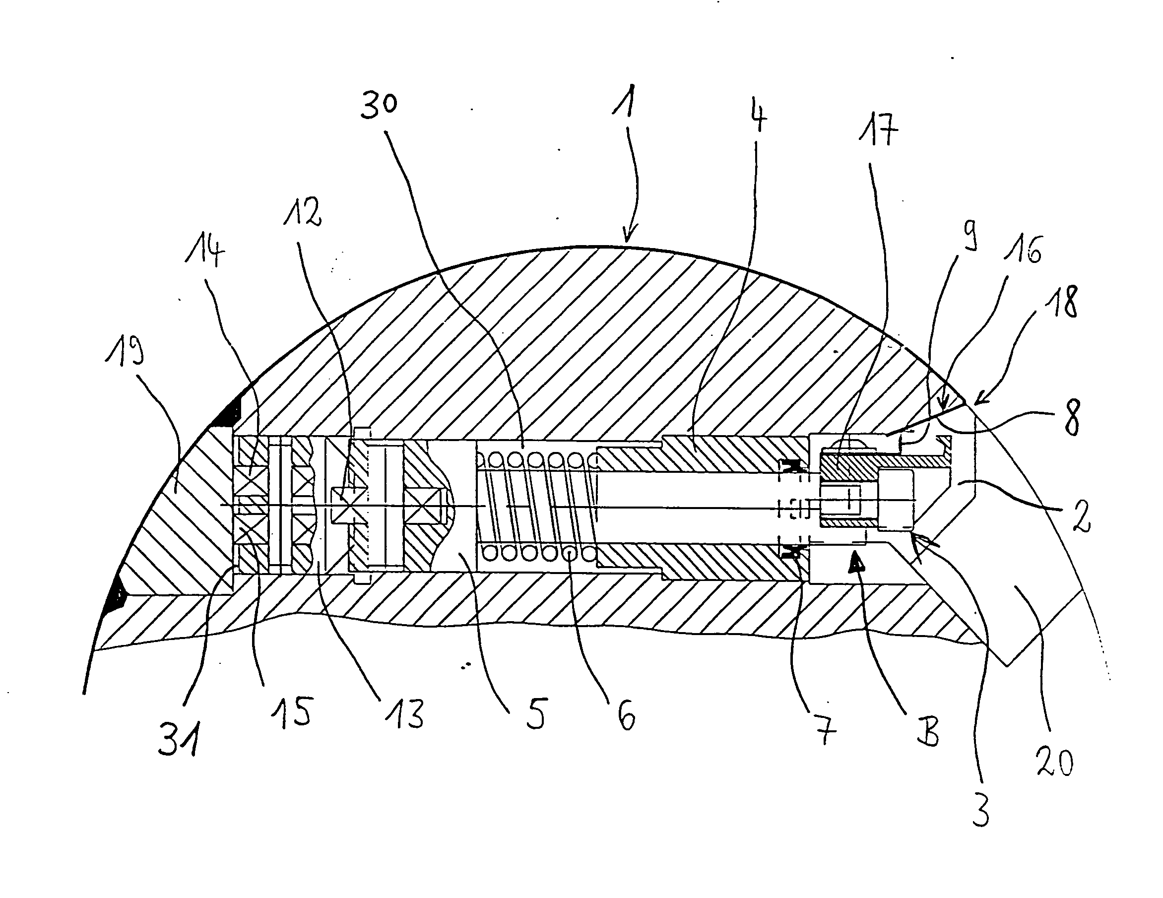
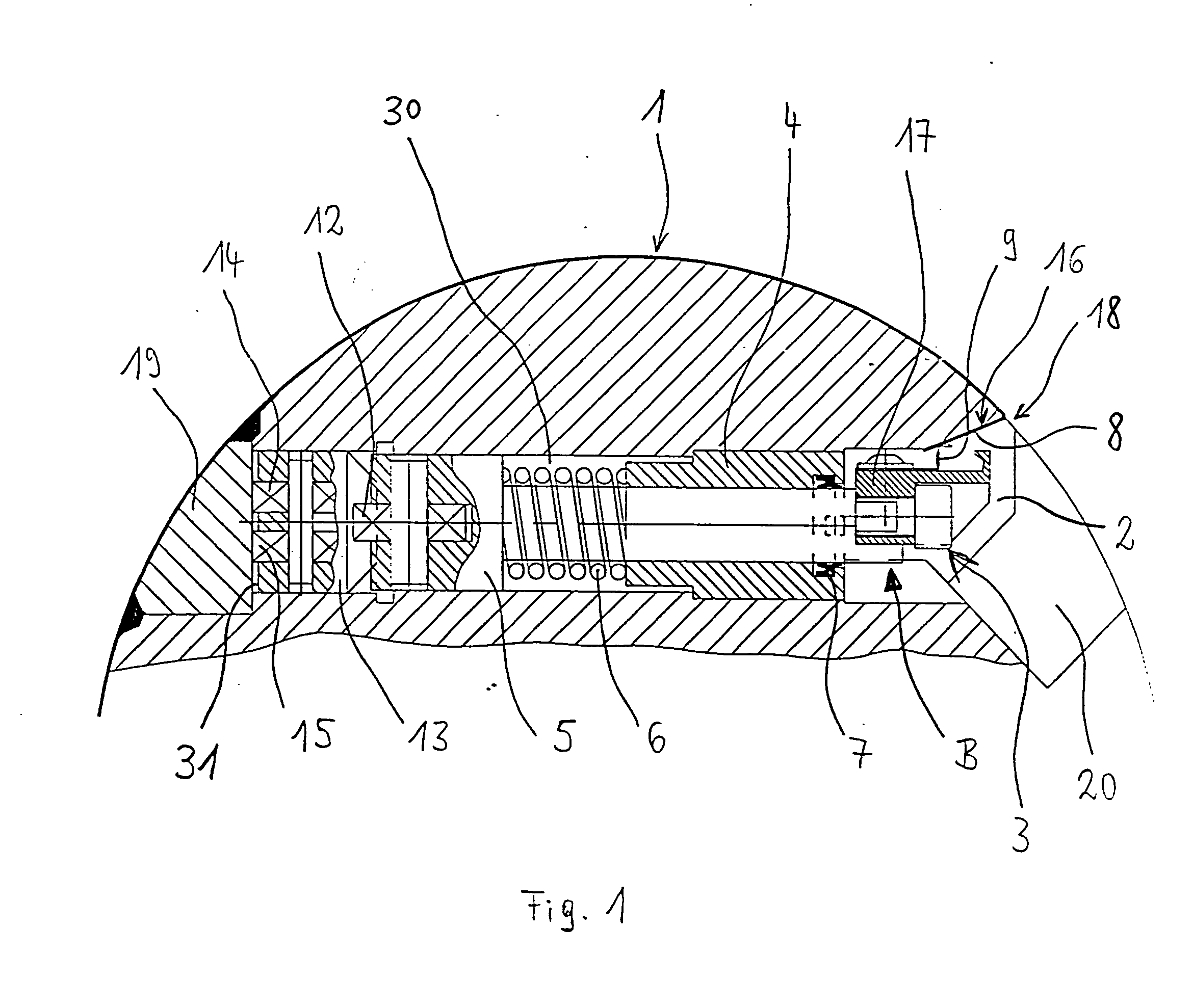
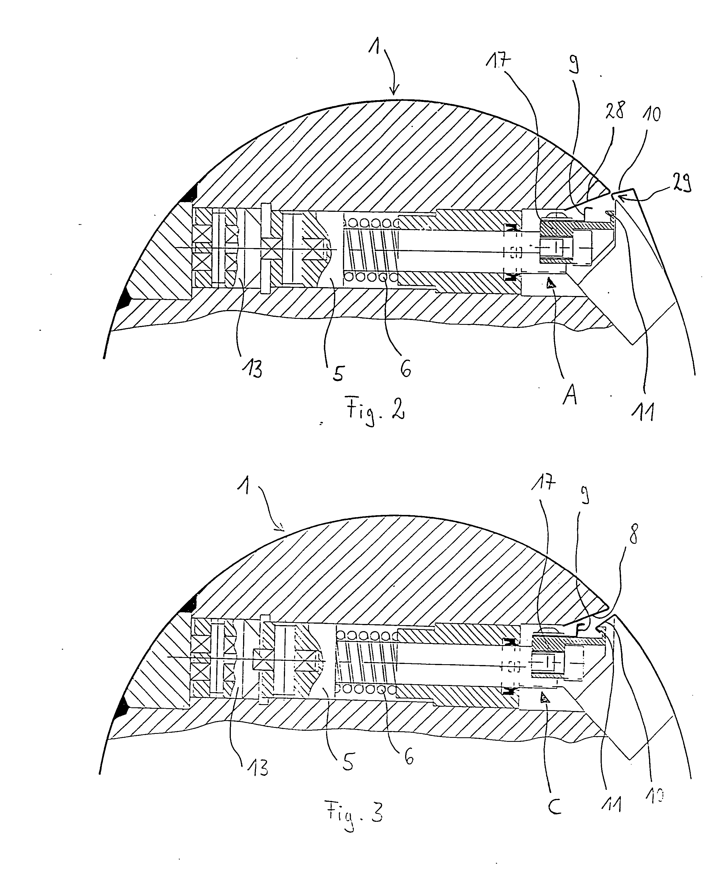
[0022] FIG. 1 shows part of a plate cylinder 1 having a cut-out 2 which extends in its longitudinal direction and can be a channel-like milled-out section, in which a clamping device 3 is arranged. The clamping device 3 has a guide element 4 which is fastened in a bore 30. A plunger 5 is displaceably mounted in the guide element 4, the plunger 5 being pressed inwards by a compression spring 6 arranged on the guide element 4. A tensioning rail 17 is arranged on at least one plunger 5. At least one tensioning rail 17 is required per printing plate. A wiping element 7 is arranged on the guide element 4, in order to wipe off dirt adhering to the plunger 5. A holding element 9 is arranged on the tensioning rail 17 for clamping a leading plate end 8. The holding element 9 is, for example, a leaf spring. The holding element 9 configured as a leaf spring can also be replaced by an appropriate shaped surface on the tensioning rail 17. A holding element 11 is arranged on the tensioning rail 1...


PUM


Abstract

A plate cylinder of a printing press, with a tensioning channel which extends in the axial direction, in which means for fixing the plate ends of at least one printing plate which can be positioned on the plate cylinder are arranged. The leading plate end can be fixed by a holding element against a contact surface by means of a tensioning rail which can be moved in the tensioning channel. After that, and after the plate cylinder has been rotated, it is then possible to hook the trailing plate end on the extended tensioning rail. After that, it is possible to draw the tensioning rail back in again to tension the trailing plate end.

Description

[0001] 1. Field of the Invention[0002] The invention relates to a plate cylinder of a printing press having an axially extending plate channel and means for fixing the leading and trailing ends of at least one printing plate in the channel.[0003] 2. Description of the Related Art[0004] U.S. Pat. No. 6,439,117 shows a device for fastening flexible printing plates to the plate cylinder, which device comprises a clamping device arranged in the cylinder body and a segmented pressure bar arranged outside the plate cylinder, this one clamping device clamping all the printing plates. A disadvantage is that the clamping device releases the ends of all the printing plates when one printing plate is changed, and for this reason, when the one printing plate is to be changed, the other printing plates which are not to be changed have to be pressed onto the plate cylinder by means of the segmented pressure bar and held, so that the ends of the printing plates which are not to be changed do not s...

Claims


Application Information

Patent Timeline
IPC IPC(8): B41F27/12
CPCB41F27/1262
Inventor KOPPELKAMM, GUNTER
Owner MANROLANAD AG
Why Eureka
Try Eureka