
Refractive adapter for close-range viewing, with devices for rotating corrective lens housed in spectacle frames

a technology of refractive adapters and spectacle frames, which is applied in the field of refractive adapters for close-range viewing, with devices for rotating corrective lenses housed in spectacle frames, and can solve problems such as bad lighting and visual field defects

Inactive Publication Date: 2004-12-09
PETROCCIONE PIERO
View PDF3 Cites 5 Cited by
  • Summary
  • Abstract
  • Description
  • Claims
  • Application Information

AI Technical Summary

Problems solved by technology

Among the enviromental causes there are insufficient and bad lighting and visual field defects, such as the capacity to measures details (very small print, miniature objects in the electronics and other industries), limited contrast (many modern print types), rythmic or continues movements (chain processes, reading while travelling).

Method used


Image

  • Refractive adapter for close-range viewing, with devices for rotating corrective lens housed in spectacle frames
  • Refractive adapter for close-range viewing, with devices for rotating corrective lens housed in spectacle frames
  • Refractive adapter for close-range viewing, with devices for rotating corrective lens housed in spectacle frames

Examples


Embodiment Construction

[0009] A specific embodiment of the invention will now be described by way of example with reference to the accompanying drawing in which:

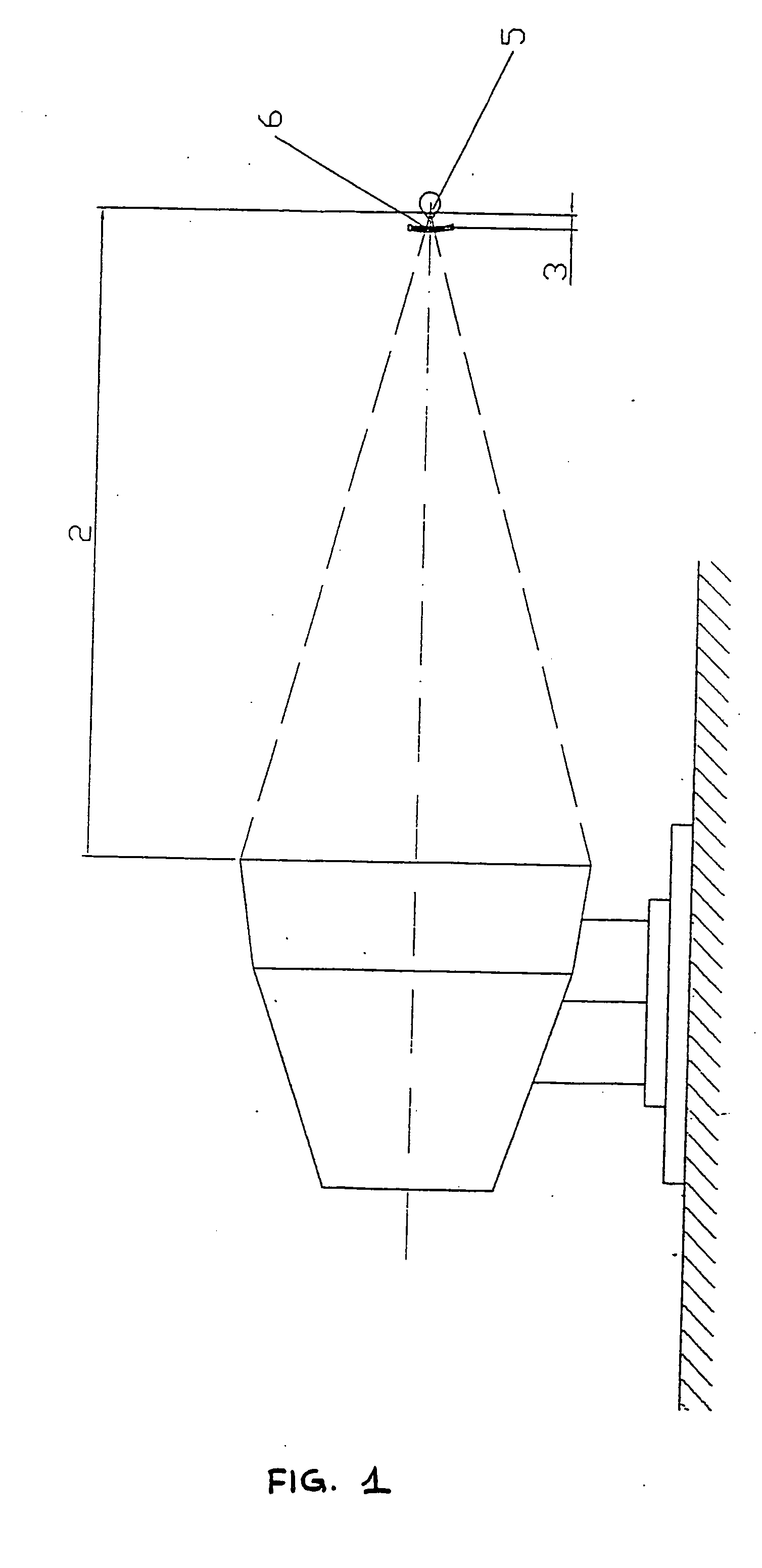
[0010] FIG. 1 shows the starting point of the study, where: (2) is the distance netween the cornea (5) of the oerator and the monitor screen (assumed to be a 19" monitor), with (2)=60 cm; and

[0011] (3) is the distance between the cornea and the lens (6), with 12 mm.ltoreq.(3).ltoreq.14 mm.

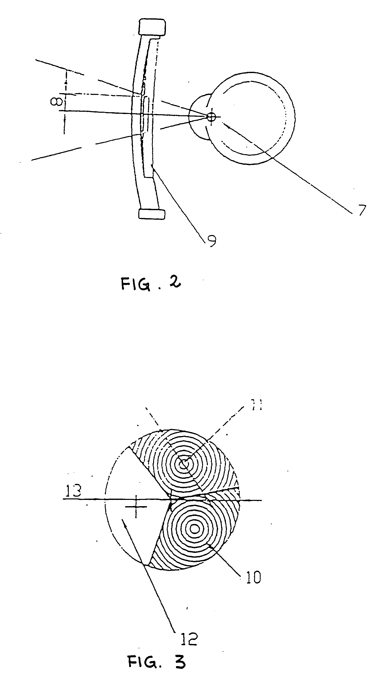
[0012] FIG. 2 shows the solid angle with apex in the pupil (7) and sufficient to enclose the screen at the distance (2), this produces the minimum radius (8) of the corrective surface. The drawing also shows the lens (9) containing the three different refractive areas.

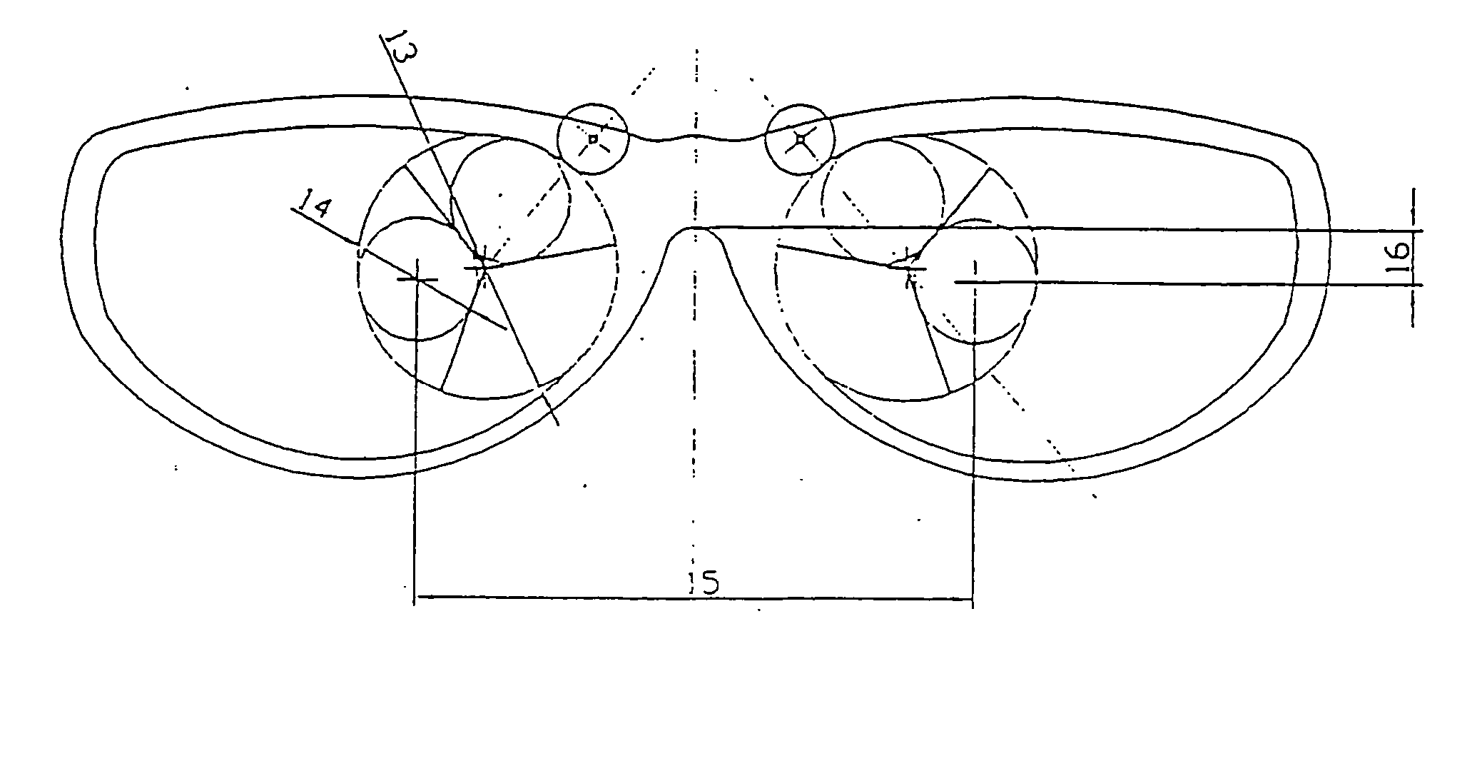
[0013] FIG. 3 shows a front view of the lens (9) with diameter (13), featuring three different refractive surfaces with differing strength, (10), (11) and (12) respectively, with diameter (14).

[0014] FIG. 4 shows an overall front view of the system, where: (15) is the distance between the pupils, wi...


PUM


Abstract

A refractive adapter for correcting accomodation disorders caused by prolonged exposure to video terminals or work involving minute objects and for helping to reduce eye strain caused by excessive visual stress at work or in leisure activites. The system comprises rotating corrective lens of various stengths, to be used as required, housed inside the spectacle frame. Rotation occurs by apllying pressure with a fingertip on the projecting lens housed in the frame slots, or by friction of a motor, consisting of a bearin with an outer surface in plastic to ensure a high friction coefficient with the moving body. The controls may be either mechanical (powered with a touch of the finger) or electromechanical (powered by a light source). The system may be an actual spectacle frame with mounted lens or a device apllied to an existing frame.

Description

[0001] This invention relates to a device for helping the eye to adapt during prolonged work at videoterminals, which feature intensive light radiation from the monitor screens; and for correcting eye strain due to visual stress at work or in leisure activities.BACKGROUND OF ART[0002] The causes of eye strain are many and not all easily identifiable; generally speaking, they may be broken down into enviromental, ocular and systemic causes.[0003] Among the enviromental causes there are insufficient and bad lighting and visual field defects, such as the capacity to measures details (very small print, miniature objects in the electronics and other industries), limited contrast (many modern print types), rythmic or continues movements (chain processes, reading while travelling).[0004] Secondly, eye strain may be due to ocular (or eye-related) causes, such as non-corrected ametropias, phoria, convergence and merging deficits, aniseiconia and, aboveall, accomodation disorders, wherefore i...

Claims


Application Information

Patent Timeline
IPC IPC(8): G02C7/00
CPCG02C7/086
Inventor PETROCCIONE, PIERO
Owner PETROCCIONE PIERO
Learn More