Measuring instrument

a technology of measuring instruments and vibration attenuation mechanisms, which is applied in the direction of instruments, measurement devices, and error compensation/elimination, etc., can solve the problems of inability to ignore the vibration generated when the probe and the table are relatively moved, the limitation of the vibration attenuation mechanism, and the inability to efficiently produce the casting member

Active Publication Date: 2004-12-16
MITUTOYO CORP
View PDF6 Cites 20 Cited by
  • Summary
  • Abstract
  • Description
  • Claims
  • Application Information

AI Technical Summary

Benefits of technology

[0010] According to this arrangement, since the at least one assembly out of the assemblies of the movable member or the guide member which supports the movement of the movable member has the sealed space in which a filler is filled, rigidity and vibration attenuation ability can be enhanced as compared to a typical assembly with rib configuration. Specifically, by enhancing the rigidity, the generated residual vibration can be reduced, and by filling the filler in the sealed space, the generated residual vibration can quickly be attenuated. Accordingly, even when the measurement is performed after the residual vibration is attenuated for highly accurate measurement, the measurement standby time can be shortened, thus highly improving the measuring speed and the measuring accuracy.
[0022] According to this arrangement, since the core sand used for the formation of the sealed space is filled in the sealed spaces of the horizontal beam and the table, a process for removing the core sand from the sealed spaces when the horizontal beam and the table are manufactured can be omitted. Accordingly, a process for filling another filler in the sealed spaces can be omitted. Thus, the manufacturing process of the horizontal beam and the table can be facilitated, consequently enhancing the manufacturing efficiency.

Problems solved by technology

However, with the measuring speed and the measuring accuracy highly improved, vibration generated when the probe and the table are relatively moved cannot be ignored.
However, the vibration attenuation mechanism has the limitation of attenuating the vibration.
Thus, there has been a disadvantage that the casting of the guide and the table need numerous steps, thus not efficiently producing the casting member.
Furthermore, since the table is formed with the casting member, the secular change of the table can be restricted.

Method used


Image

  • Measuring instrument
  • Measuring instrument
  • Measuring instrument

Examples


Embodiment Construction

)

[0029] An embodiment of the present invention will be described below with reference to the attached drawings.

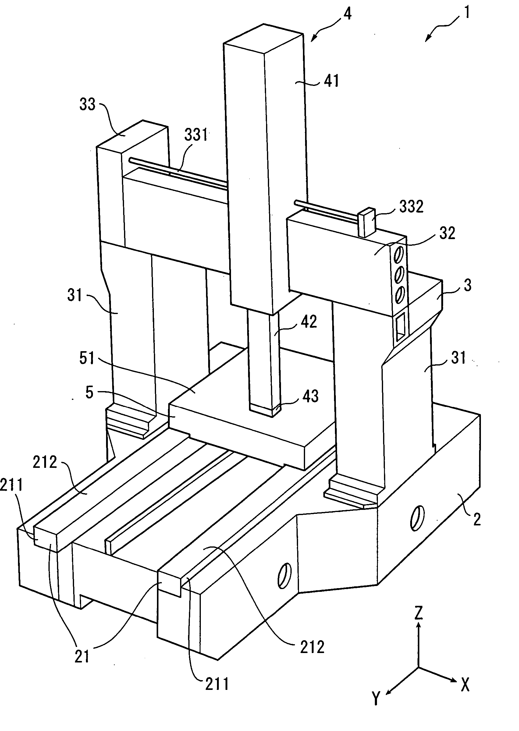
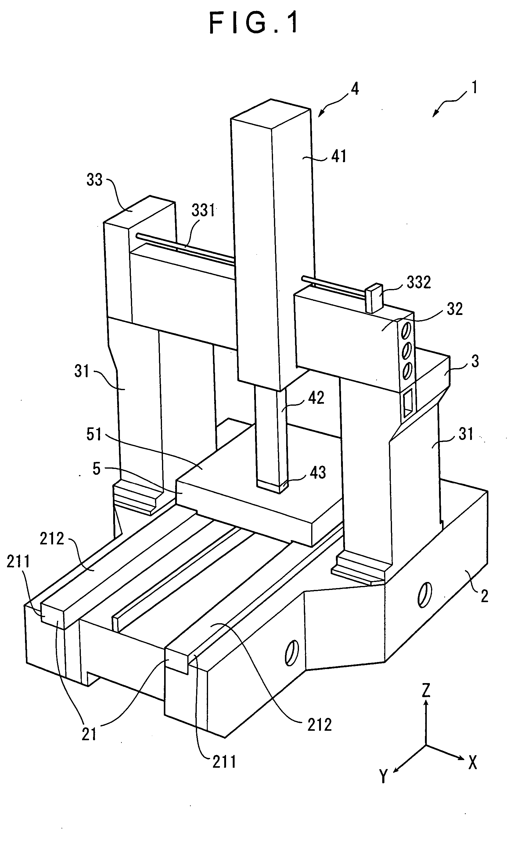
[0030] FIG. 1 shows a coordinate measuring machine according to the present embodiment.

[0031] Referring to FIG. 1, a coordinate measuring machine 1 includes a base 2, a bridge type column 3, a slider 4 and a table 5.

[0032] The base 2, which is a base of the coordinate measuring machine 1, is made of a casting member. A Y-axis guide 21 is provided on an upper side of the base 2. The Y-axis guide 21 guides the table 5 sliding in a longitudinal direction of the coordinate measuring machine 1, i.e., in Y-axis direction as shown in FIG. 1 with a sign "Y". The Y-axis guide 21 includes rails 211, which are two substantially projected guide members formed along the longitudinal direction of the base 2 with being parallel to each other. A guide way 212 that guides the table 5 sliding is formed on each upper side of the rails 211.

[0033] The bridge type column 3 is vertically provided...


PUM


Abstract

At least one assembly of a movable member or a guide member (32) that guides the movement of the movable member out of a plurality of assemblies of a measuring instrument contains a sealed space (322). A filler is filled in the sealed space (322). According to this arrangement, rigidity of the movable member or the guide member (32) can be enhanced. Further, residual vibration generated along with the movement of the movable body can efficiently be attenuated.

Description

[0001] 1. Field of the Invention[0002] The present invention relates to a measuring instrument. Particularly, the present invention relates to a measuring instrument that includes a plurality of assemblies, at least one assembly of which serves as a movable member or a guide member for supporting a movement of the movable member.[0003] 2. Description of Related Art[0004] Conventionally, a coordinate measuring machine for measuring three dimensional data such as dimension and profile of a workpiece has been known (for example, see JP2000-65561A). In the above coordinate measuring machine, a probe and a table can relatively be moved in three axial-directions of X, Y and Z-axis directions being orthogonal each other to measure the three dimensional data such as the dimension and the profile of the workpiece based on a movement displacement amount of each axis when the probe contacts the workpiece set on the table.[0005] Currently, the above coordinate measuring machine has been highly ...

Claims


Application Information

Patent Timeline
Patent Type & Authority Applications(United States)
IPC IPC(8): G01B21/00F16F7/01F16F15/02G01B5/00G01B5/008
CPCF16F7/01F16F15/02G01B5/0011G01B5/008
Inventor OGURA, KATSUYUKIYAMAZAKI, KENJI
Owner MITUTOYO CORP
Why Eureka
Try Eureka