Laser digitizer system for dental applications

Inactive Publication Date: 2004-12-16
D4D TECH LP
View PDF12 Cites 81 Cited by
  • Summary
  • Abstract
  • Description
  • Claims
  • Application Information

AI Technical Summary

Benefits of technology

0032] FIG. 15 illustrates an intra-oral digitizer with a low coherence light source cou

Problems solved by technology

Such systems have low depth resolution and may not accurately image or represent a surface that is undercut or shadowed

Method used


Image

  • Laser digitizer system for dental applications
  • Laser digitizer system for dental applications
  • Laser digitizer system for dental applications

Examples


Embodiment Construction

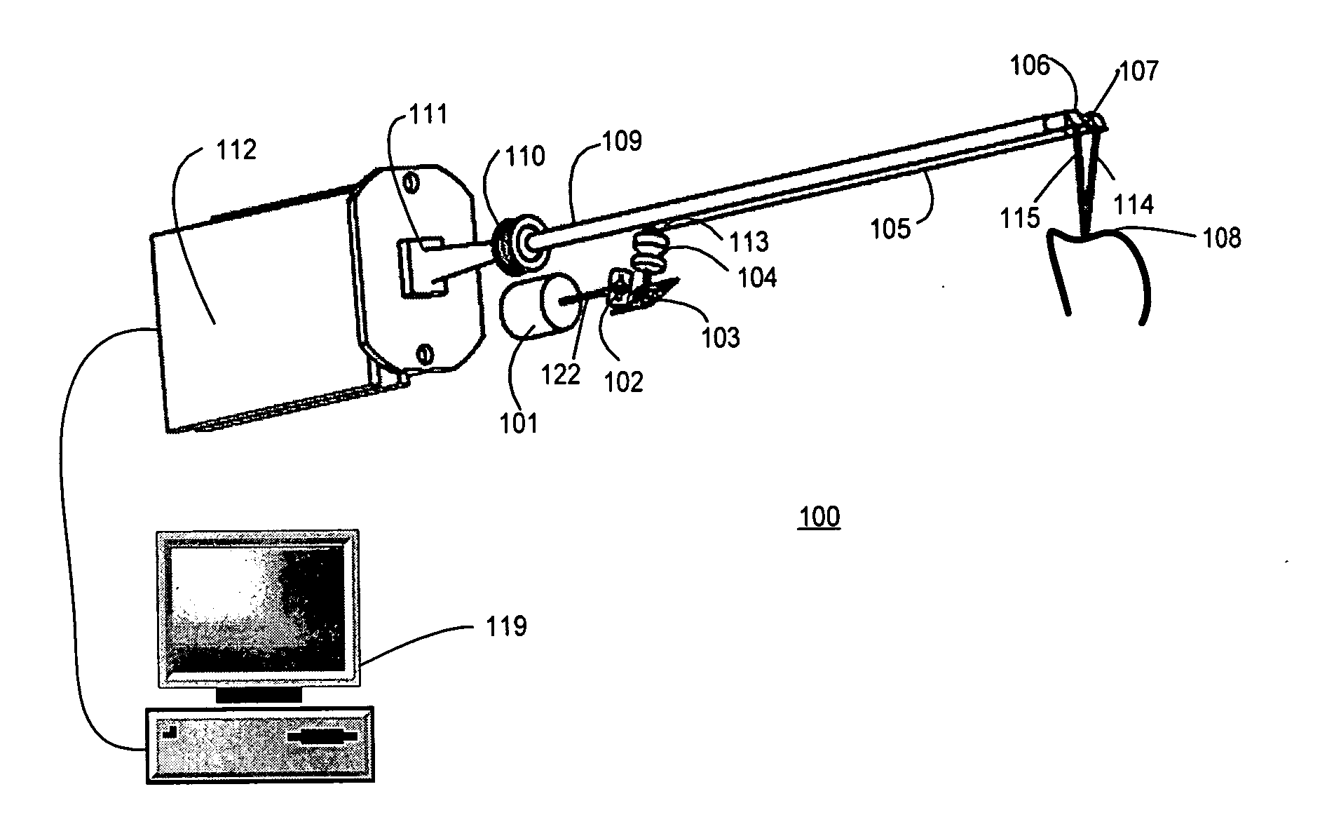
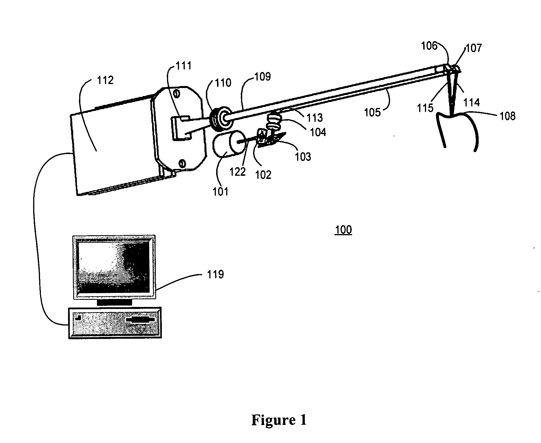
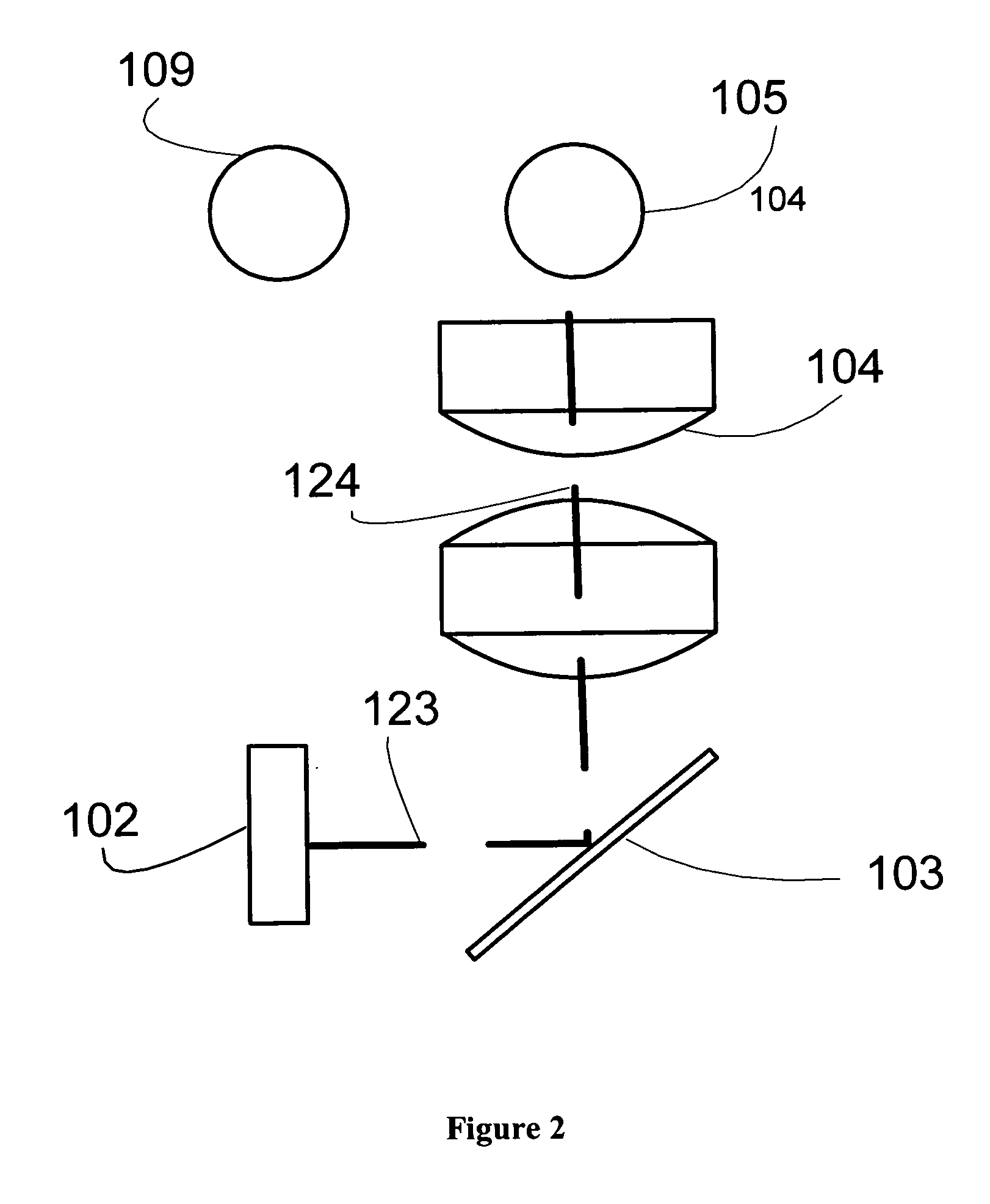
[0033] FIG. 1 illustrates an example of an intra-oral laser digitizer 100. FIGS. 2-5 illustrate various views of the intra-oral laser digitizer 100 of FIG. 1. The intra-oral digitizer 100 generates a 3D image of an object 108 such as a dental item. The intra-oral digitizer 100 generates a laser pattern that may be projected on or towards a dental item, dentition, or prepared dentition in an oral cavity (in vivo). The intra-oral digitizer 100 may remotely generate the laser pattern and relay the pattern towards the dental item or items in vivo. The laser pattern may be relayed through relay optics such as prisms, lenses, relay rods, fiber optic cable, fiber optic bundles, or the like. The intra-oral digitizer 100 also may detect or capture light reflected from the dental item in vivo. The intra-oral digitizer 100, or a portion thereof, may be inserted in the oral cavity to project the laser pattern and to detect the reflected laser pattern from the dental item or items in the oral ca...


PUM


Abstract

A intra-oral laser digitizer system provides a three-dimensional visual image of a real-world object such as a dental item through a laser digitization. The laser digitizer captures an image of the object by scanning multiple portions of the object in an exposure period. The intra-oral digitizer may be inserted into an oral cavity (in vivo) to capture an image of a dental item such as a tooth, multiple teeth or dentition. The captured image is processed to generate the three-dimension visual image.

Description

PRIORITY AND CROSS REFERENCE TO RELATED APPLICATION[0001] This application claims the benefit under 35 U.S.C. .sctn. 119(e) of co-pending provisional application no. 60 / 457,025 for Intra-Oral Laser Digitizer System For Dental Applications, which is incorporated in its entirety herein by reference.[0002] 1. Related Field[0003] The invention relates to three-dimensional imaging of physical objects. In particular, the invention relates to intra-oral (in vivo) laser imaging of dental items including dentition, prepared dentition, impression materials and the like.[0004] 2. Description of the Related Art[0005] A three-dimensional ("3D") visual image of a physical object may be generated by a computer that processes data representing shapes, surfaces, contours and / or characteristics of the object. The data is generated by optically scanning the object and detecting or capturing the light reflected from the object. Principles such as Moir, interferometry, and laser triangulation, may be us...

Claims


Application Information

Patent Timeline
IPC IPC(8): A61B5/107A61B6/00A61B6/14A61C9/00A61C19/04G01BG01B1/00G01B11/24G01B11/25
CPCA61B5/0066A61B5/0088A61B5/1077A61B5/4547G01B11/24G01B11/25G01B11/2518A61C9/0053A61B1/24
Inventor QUADLING, HENLEYQUADLING, MARKBLAIR, ALAN
Owner D4D TECH LP
Why Eureka
Try Eureka