Motor Controller

a technology of motor controller and control panel, which is applied in the direction of motor/generator/converter stopper, dynamo-electric converter control, instruments, etc., can solve the problems of increased detection circuit and electronic switch, motor becomes non-controllable, and increase the number of feed back detectors

Inactive Publication Date: 2004-12-23
ROCKWELL AUTOMATION TECH +1
View PDF2 Cites 48 Cited by
  • Summary
  • Abstract
  • Description
  • Claims
  • Application Information

AI Technical Summary

Benefits of technology

[0017] In this way, it is possible to perform a safe and highly reliable motor driving control even in the case where there occurs the abnormality in the feed back detectors for detecting the magnetic pole position or velocity of the rotor of the synchronous motor and the feed back signals are not outputted at all from these detectors.

Problems solved by technology

In the case where signal from the feed back detector becomes abnormal due to a defect of the feed back detector, the motor becomes non-controllable since it is not possible to find the position and velocity of the rotor of the motor.
However, such a method increases the number of feed back detectors and, accompanied with this increase, detection circuits and electronic switches are increased.
As a result, comparing to the case of a single feed back detector, the number of parts is increased, thereby causing a problem in that the reliability of the parts is lowered.
This finally leads to the lowering of the reliability of the whole controller and, further, causes a problem in that an installation area is increased and costs are driven up.
In such a motor controller, in addition to the feed back detector for detecting the position and velocity of the rotor of the synchronous motor, a CS signal detector for detecting a commutation signal is provided to detect a magnetic pole position of the rotor of the synchronous motor and, therefore, in the case where the detection functions of these detectors all become abnormal, there arises a problem in that all the references of a comparison to see whether it is good or bad cease to exist, so that the detection or judgment of the abnormality becomes absolutely impossible with a result that it is no longer possible to control the motor.

Method used


Image

  • Motor Controller
  • Motor Controller
  • Motor Controller

Examples


Embodiment Construction

[0028] An embodiment of the present invention will be described below with reference to the drawings.

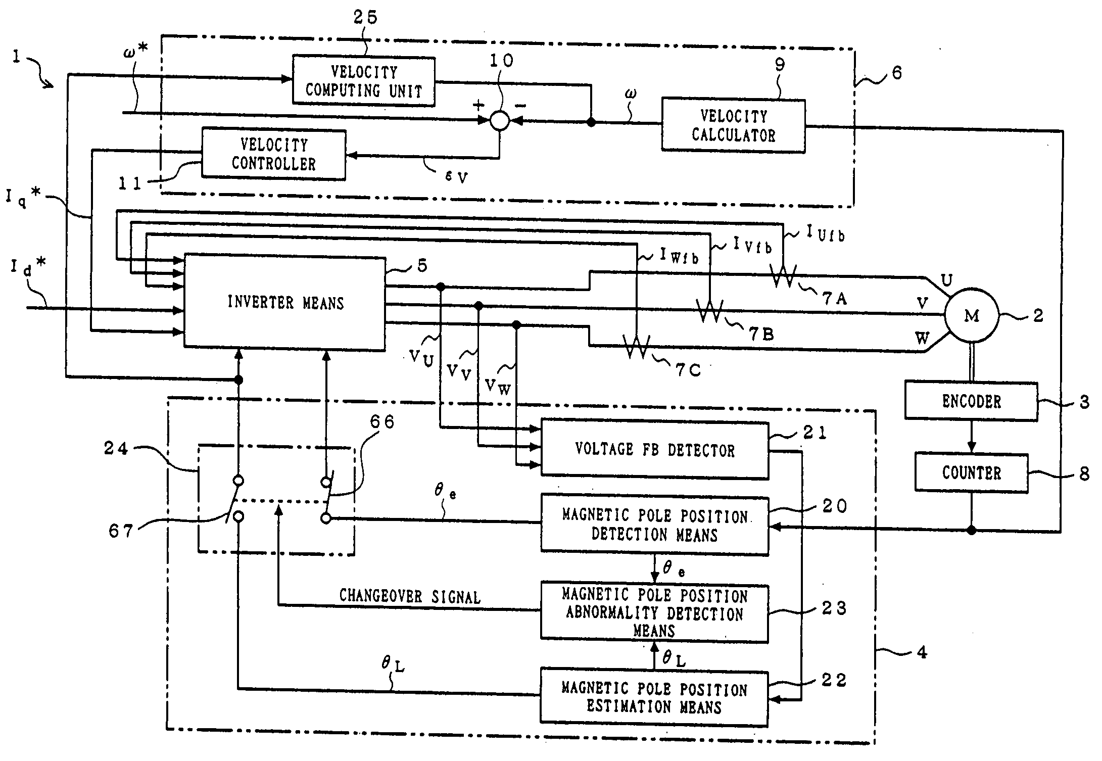
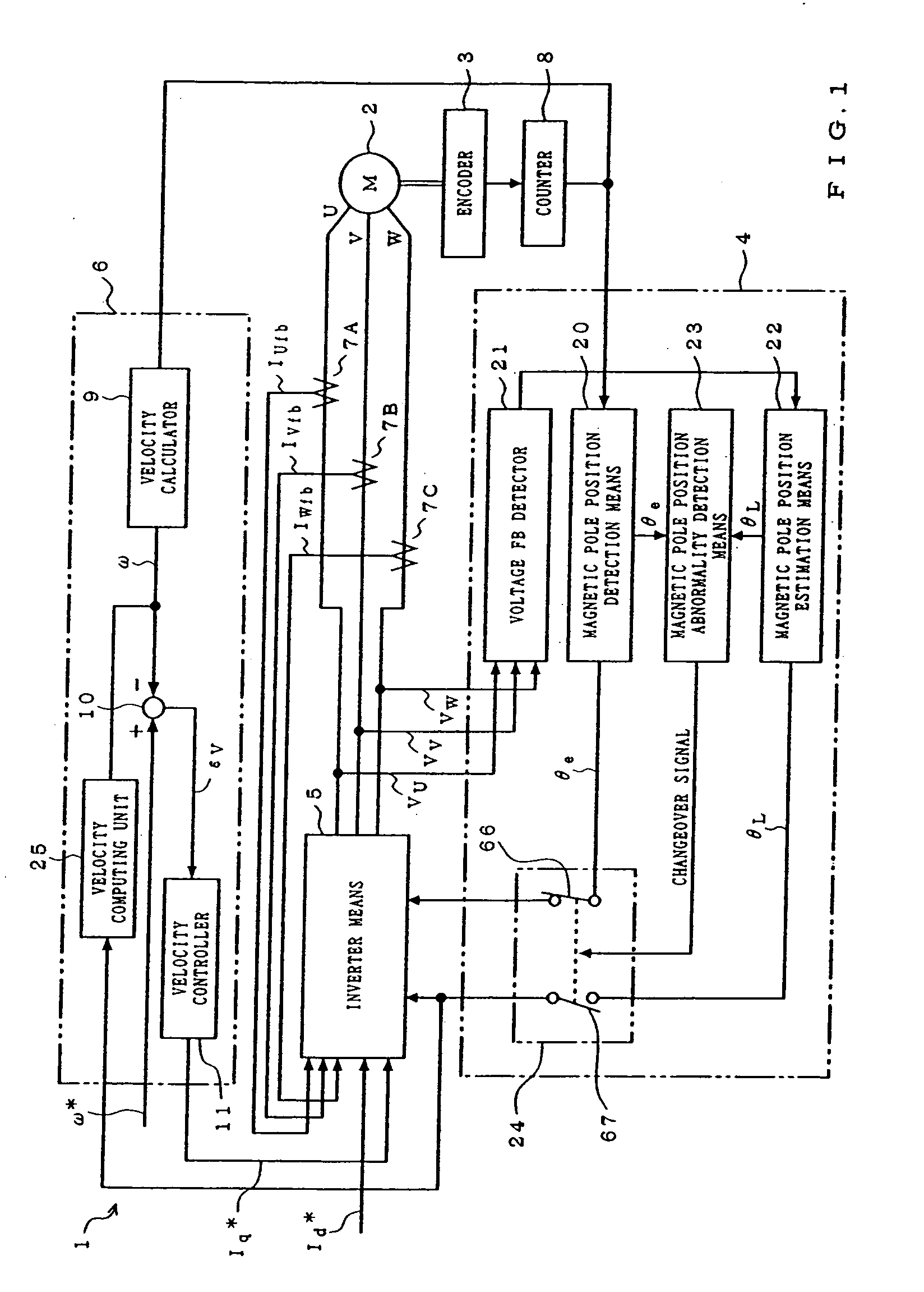
[0029] FIG. 1 is a block diagram showing one embodiment of a motor controller 1 according to the present invention. The motor controller 1 is constituted by sensor control means 4, inverter means (or vector control means) 5, velocity control means 6, current detectors 7A, 7B and 7C, an encoder 3, and an encoder counter 8. The encoder 3 is an absolute value rotary encoder, and is a feed back detector (sensor) for use of a position and velocity detection mounted on a rotational axis of a brushless synchronous motor 2 (hereinafter, referred to as the motor), which is a control object of the motor controller 1.

[0030] The sensor control means 4 is constituted by magnetic pole position detection means 20, voltage feedback (FB) detector 21, magnetic pole position estimation means 22, magnetic pole position abnormality detection means 23 and a sensor signal switch 24.

[0031] The velocity cont...


PUM


Abstract

A motor controller is provided. This motor controller comprises, a synchronous motor, a feed back detector which is mounted on the synchronous motor and detects the position and velocity of the rotor of the synchronous motor, magnetic pole position detection means for detecting an magnetic pole position of the rotor of the synchronous motor, inverter means for controlling an electric power to be supplied to the synchronous motor according to the magnetic pole position detected by the magnetic pole position detection means, magnetic pole position estimation means for estimating the magnetic pole position of the rotor of the synchronous motor from the induced voltage of the stator windings of the synchronous motor, and magnetic pole position abnormality detection means for detecting the abnormality of the feed back detector by always comparing the magnetic pole position detected by the magnetic pole position detection means and the estimated magnetic pole position estimated by the magnetic pole position estimation means.

Description

[0001] 1. Technical Field of the Invention[0002] The present invention relates to a motor controller and, more particularly, to a motor controller capable of performing a safe and highly reliable motor control in the case where a trouble arises particularly in a sensor for detecting a position or a velocity of the rotor of a synchronous motor.[0003] 2. Prior Art[0004] In general, a controller for controlling a synchronous motor has been used conventionally to find the position and velocity of the rotor of a motor from information of a sensor mounted on the motor, that is, a feed back detector. In the case where signal from the feed back detector becomes abnormal due to a defect of the feed back detector, the motor becomes non-controllable since it is not possible to find the position and velocity of the rotor of the motor. Hence, the motor is stopped by being allowed to make a free running or by means of a brake mechanically mounted on a motor shaft.[0005] Further, in addition to a ...

Claims


Application Information

Patent Timeline
Patent Type & Authority Applications(United States)
IPC IPC(8): H02P6/12G05B1/06H02P1/18H02P1/46H02P6/16H02P6/18H02P21/06H02P21/14
CPCH02P21/0042H02P21/146H02P2207/05H02P21/18H02P21/26
Inventor MATSUO, TAKAYOSHITANABE, SATOSHIYOSHINO, MASAZUMI
Owner ROCKWELL AUTOMATION TECH
Why Eureka
Try Eureka