Modular plastic flooring

a technology of plastic flooring and modules, applied in the field of floor coverings, can solve the problems of sportspeople's tripping problems, independent and additional costs, and achieve the effect of reducing the cost of installation and maintenan

Inactive Publication Date: 2004-12-23
DESIGN DEV COMMLISE
View PDF35 Cites 74 Cited by
  • Summary
  • Abstract
  • Description
  • Claims
  • Application Information

AI Technical Summary

Benefits of technology

[0015] The body may have apertures through it to allow water to drain off the upper surface so that the surface is not hazardous.
[0032] The larger shaped tiles mean fewer edges which limit the effective use of the tile as a ball or hockey puck contacting surface. The larger shaped tiles also mean that fewer tiles are necessary to lay and therefore enabling quicker assembly and disassembly. It also means that there may be less distortion through differential thermal expansion and contraction, therefore, providing a flatter playing surface. There are also fewer lifting corners or edges which can create safety hazards.

Problems solved by technology

Although interlocking tile floors have grown in popularity because of their versatility, there have been problems during their use.
One problem is that square or rectangular tiles which are easy to lay out and to join together have provided long lines of joins which can deflect hockey pucks and balls traveling over the surface.
Also square or rectangular tiles have become distorted which have caused corners of tiles to lift which can cause tripping problems for sports people.
This is a separate component to the flooring system, which has to be laid independently and also an additional cost.

Method used


Image

  • Modular plastic flooring
  • Modular plastic flooring
  • Modular plastic flooring

Examples


Embodiment Construction

[0054] Now looking more carefully at the drawings and in particular a first preferred embodiment of the shaped tiles and shaped connector tiles and their methods of connection as shown in FIGS. 1 to 10.

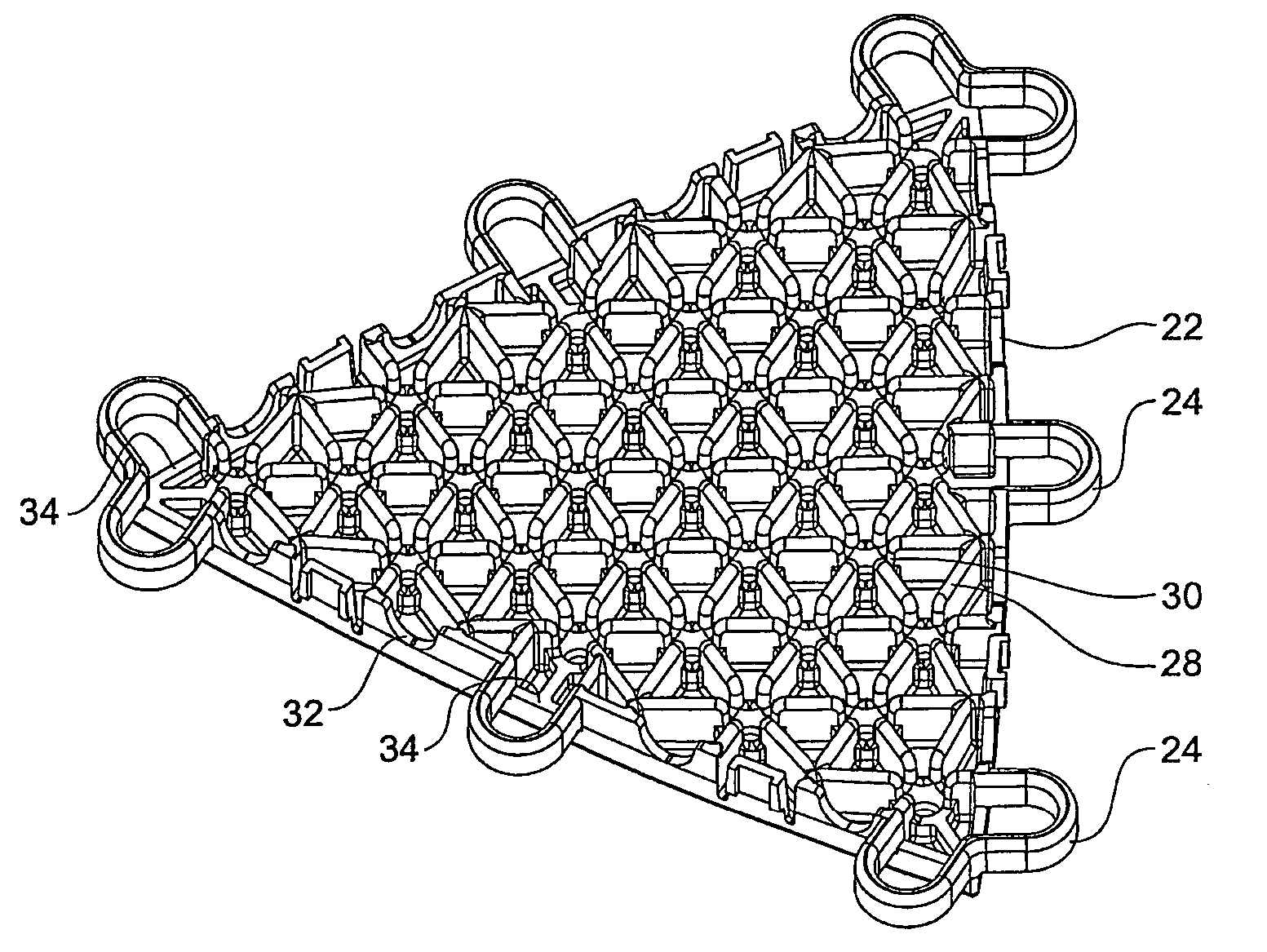
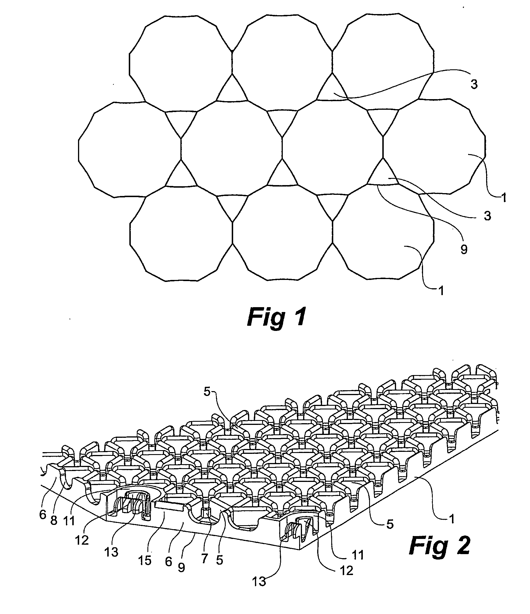
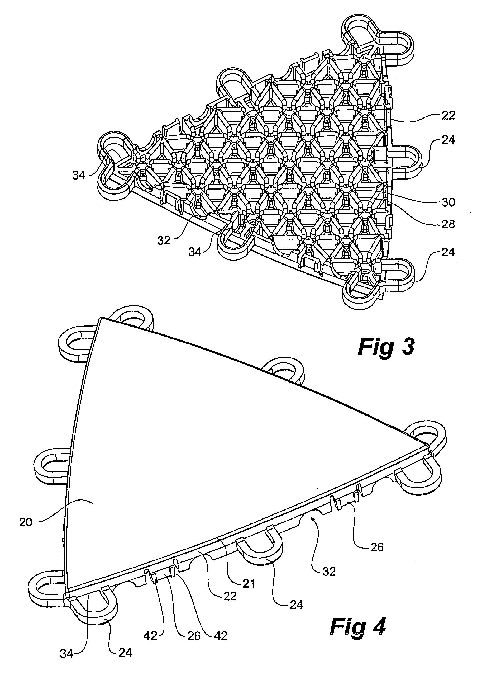
[0055] In FIG. 1 it will be seen that the shaped tiles 1 are in the shape of a dodecagon with twelve sides but that six of the sides are slightly concave. Each shaped tile abuts with another shaped tile 1 but as will be discussed in relation to further drawings there are no connectors on these abutting faces. Connection is provided through a shaped connector tile 3 which is of a substantially triangular shape but with three convex sides. Each shaped connector tile 3 abuts three shaped tiles 1.

[0056] It will be noted that there are no long straight lines of join between the various tiles which if used would create a directional bias to give problems when playing sports on the floor.

[0057] In one preferred embodiment of the invention the diameter of the shaped tiles is 500 mm and there ...


PUM

PropertyMeasurementUnit
distanceaaaaaaaaaa
diameteraaaaaaaaaa
diameteraaaaaaaaaa

Abstract

A modular plastic floor assembly formed from a plurality of shaped tiles (1) and a plurality of shaped connector tiles (3). The shape tiles are substantially larger than the shaped connector tiles and the shaped connector tiles fit into interstices between the shaped tiles when the floor assembly is formed. Each of the shaped tiles and the shaped connector tiles have a substantially planar upper surface (20) and a support array (5, 28) extending from a lower surface of the body. The shaped tiles have connectors (11) and the shaped connector tiles have complementary connectors (24). The connectors are adapted to interengage to interlock the shaped tiles to adjacent shaped connector tiles. Resiliently loaded fingers (118) allow for expansion and contraction between the adjacent tiles. The support array may include resiliently moulded shock absorbing portions (141). The upper surface may have in-mould decoration to provide a surface with changed appearance, frictional properties and / or surface hardness.

Description

[0001] This invention relates to plastic material tiles which are supported on a surface to provide a playing surface for recreational games and a temporary flooring surface for special events. More particularly the present invention pertains to modular tiles of plastic composition which are interlocked to form a playing surface.BACKGROUND TO THE INVENTION[0002] A wide variety of floor coverings have been developed for use as playing surfaces for sports. Interlocking plastic tile floor coverings have grown in popularity due to their shock absorbent characteristics, which can help prevent injury to athletes, their versatility (can be indoor or outdoor) and affordability. Plastic flooring can also be quickly installed and removed for special events and sports competitions.[0003] Structurally interlocked tile floor coverings generally comprise several interlocked plastic tiles in a grid like configuration. Each tile may have an underside provided with a rib arrangement and support legs...

Claims


Application Information

Patent Timeline
Patent Type & Authority Applications(United States)
IPC IPC(8): E01C5/20E01C13/04E04F15/10E04F15/22
CPCE01C5/20E01C13/045Y10T428/16E04F15/10E04F15/22E01C2201/12E04F15/02194E04F15/105
Inventor WALKER, ALEXANDER WILLIAM
Owner DESIGN DEV COMMLISE
Why Eureka
Try Eureka